Grove Published 01-29-2015, Control # 512-01 8-51
TMS700E SERVICE MANUAL UNDERCARRIAGE
a. The Air Pressure Low Light and warning buzzer will
come on when the secondary air pressure drops
below 5.17 ± 0.34 bar (75 ± 5 psi).
b. The pressure in the secondary circuit should not
drop below 5.90 ±0.34 bar (85 ±5 psi).
c. Depressurize the secondary system to zero.
16. Check that all the wheels can be rotated.
17. Apply the service brakes.
a. The rear front axle and the rear axles’ service
brakes should be applied and the brake lights on the
rear of the carrier should be on.
b. Release the service brakes and check that all
wheels turn freely.
c. Close the drain valves and recharge the system.
18. Apply the parking brakes.
19. Lower the crane to the ground off the outriggers.
20. With the engine running, position the Suspension
Control Valve Lever to the INFLATE position to inflate
the air suspension bags. The Amber Deflate Indicator
light should go out when the pressure in the air bags
goes above 0.28 ± 0.14 bar (4 ± 2 psi).
21. Continue charging the system until the air dryer cycles
and the compressor shuts off. All system gauges should
read 9.30 bar (135 psi).
22. Check that all suspension air bags are properly inflated.
The top surface of each air bag saddle should be parallel
with the bottom horizontal surface of the carrier frame.
AIR SYSTEM COMPONENTS
Description
Air Compressor
The air compressor is mounted on and driven by the engine.
It provides the source of compressed air for the operation of
the air system components. It is controlled (cycled on and
off) by an air governor. The compressor has a capacity of
0.53 cm/m (18.7 cf/m).
Air Governor
The air governor is mounted on the left side of the air dryer.
The governor senses the system pressure and when
pressure reaches 9.30 bar (135 psi) the governor vents the
compressor. When pressure drops to 7.90 bar (115 psi), the
governor signals the compressor to start charging again.
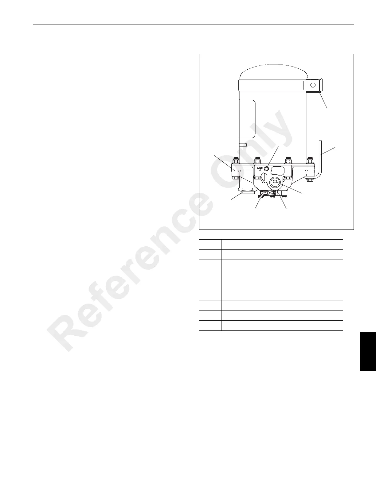
Air Dryer
The purpose of the air dryer (see Figure 8-40) is to collect
and remove solid, liquid, and vapor contaminates from the
air system. Clean dry air increases the life of the air system
and reduces cost.
The dryer consists of a desiccant cartridge and die cast
aluminum end cover secured to a cylindrical steel shell. The
end cover contains a check valve, safety valve, three
threaded connections and purge valve housing. The purge
valve housing contains the purge valve and turbo charger
cutoff. The turbo charger cutoff prevents loss of engine
“turbo” boost pressure during the purge cycle of the air dryer
Item Description
1 End Cover
2 Control Port
3 Upper Bracket
4 Lower Bracket
5 Delivery Port
6 Female Connector
7 Purge Valve Housing
8 Supply Port
Reference Only

 Loading...


