UNDERCARRIAGE TMS700E SERVICE MANUAL
8-70 Published 01-29-2015, Control # 512-01
plate, and for proper tracking during beam
extension and retraction.
2. Position the extension cylinder so the hydraulic ports on
the rod end of the cylinder can be accessed. Connect
the hydraulic hoses to the ports as tagged during
removal.
3. Push the cylinder into the outrigger beam. Align the
cylinder rod with the clevis in the beam. Apply anti-seeze
to the clevis pin and secure in place with the clevis pin
and cotter pin.
4. Install the outrigger beam. (Refer to Outrigger Beam -
Installation in this Section).
Functional Check
1. Activate the hydraulic system; extend and retract the
outrigger.
2. Observe the operation of the outrigger beam.
3. Check the hydraulic connections for any evidence of
leakage.
OUTRIGGER MONITORING SYSTEM
(OPTIONAL—STANDARD IN NORTH
AMERICA)
Description
The Outrigger Monitoring System (OMS) aids the operator in
accurately programming the Rated Capacity Limiter (RCL)
by automatically identifying the horizontal position of each
outrigger beam. The OMS uses four sensors, one per
outrigger beam, to identify when an outrigger beam is
positioned to one of three pre-defined locations, including
fully retracted, mid-extend, and fully extended.
Removal
1. Extend the outrigger beam slightly for improved access
and shut down the engine.
2. Remove the outer access cover plate from outrigger
box.
3. Remove the OMS string potentiometer (1, Figure 8-68)
connector (2) from the attaching point on the outrigger
beam.
NOTE: Avoid free-release of cable to prevent damage to
OMS string potentiometer.
4. Disconnect electrical harness connector and secure to
avoid damage.
5. Loosen the mounting hardware enough to disengage
OMS string potentiometer from the slotted mounting
hole.
6. Completely remove the other mounting hardware.
7. Remove OMS string potentiometer from inside outrigger
beam.
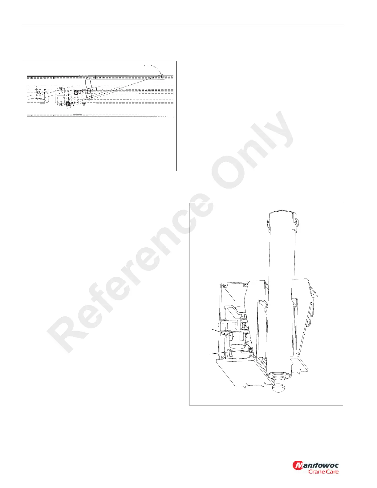
10°
FIGURE 8-67
NOTE: Keep hydraulic fittings and hoses close to angles
shown & as low as possible to prevent rubbing with
the beam top plate & side plate, and for proper
tracking during beam extension and retraction.
18°
Reference Only

 Loading...


