Grove Published 01-29-2015, Control # 512-01 5-13
TMS700E SERVICE MANUAL HOIST AND COUNTERWEIGHT
wires to the display. Replace the panel and secure with the
hardware.
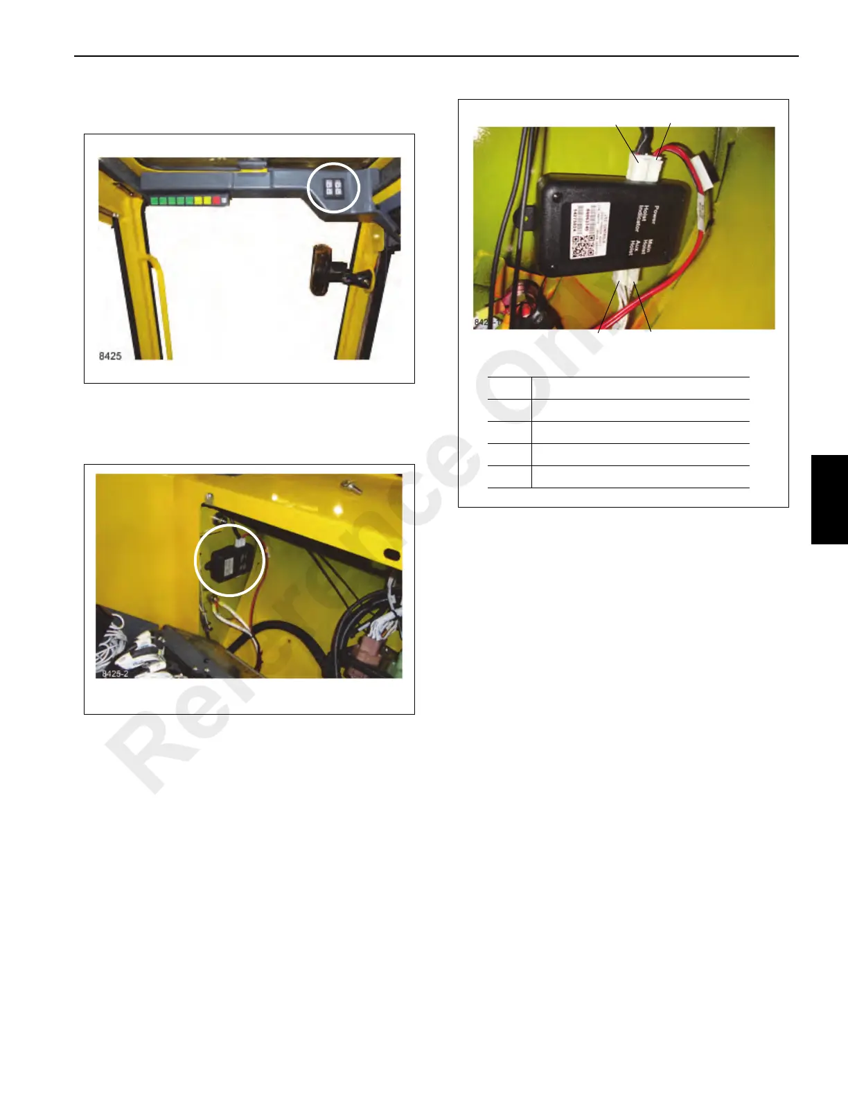
HRI Control Module
The control module is located in the fuse and relay panel
behind the driver’s seat in the cab Figure 5-8.
To replace the control module, tag and disconnect the wires
from the module Figure 5-9. The module is mounted to the
bulkhead using double-sided adhesive tape. To remove the
module, pry it off the bulkhead. Remove any residual tape
from the bulkhead. Secure the replacement module to the
bulkhead with the foam tape. Connect the wires as tagged
during removal.
HOIST CONTROL VALVES
Description
NOTE: For more detailed information, refer to Valves,
page 2-19.
Hydraulic Hoist Motor Control Valve
The hydraulic hoist motor control valve is mounted on the
hoist and is designed to provide an even flow of oil to the
hoist motor in both directions. This is a different valve than
the hoist motor control valve that applies and releases the
hydraulic piston and hydraulic cylinder.
Hoist Directional Control Valve
The hoist directional control valve is used to control the
operation of the hoist. It is a four-way, pilot operated valve
and is mounted on the right side of the turntable.
COUNTERWEIGHT
Description
The removable counterweight (see Figure 5-5) is pinned to
the rear of the turntable under the hoist mounting. The
counterweight consists of one standard box and maximum of
two slabs, each weighing 2495 kg (5500 lb). This provides
counterweight configurations of 4990 kg (11000 lb) and
7485 kg (16500 lb). The standard box contains lugs for
FIGURE 5-9
8425-1
Item Description
1 To LED Indicator
2 Power and Ground
3 Main Hoist Pressure Switches
4 Auxiliary Hoist Pressure Switches
1
2
4
3
Reference Only

 Loading...


