UNDERCARRIAGE TMS700E SERVICE MANUAL
8-50 Published 01-29-2015, Control # 512-01
Air System Operational Test
1. Park the crane on a firm level surface and apply the
parking brakes.
2. Position the Suspension Control Valve Lever to the
DEFLATE position to deflate the air suspension bags.
The amber Deflate Indicator Light should illuminate
when the pressure in all air bags drops below 0.28 ±
0.14 bar (4 ± 2 psi).
3. Raise the crane on outriggers.
4. Shutdown the engine.
5. Open the manual drain valves on the main air reservoirs
to depressurize both air circuits. If not already applied,
the parking brake will be applied as the system is
drained. Ensure the parking brakes are applied on all
rear wheels.
6. Close the drain valves and start the engine.
a. The Air Pressure Low Light and warning buzzer
should activate immediately.
b. The red (rear primary) needle on the dual air gauge
should rise to about 5.90 bar (85 psi) at which time
the green (front/secondary) needle will begin to rise.
c. The warning buzzer and light will stay on until both
gauges show 4.10 to 4.80 bar (60 to 70 psi).
d. Release the parking brake.
e. Check that the outriggers cannot be operated with
the parking brakes released.
f. Continue charging the system until the air dryer
cycles and the compressor shuts off. All system
gauges should read 9.30 bar (135 psi).
7. Turn off the engine and check that all wheels turn freely.
8. The air pressure should remain constant with no leaks.
Any air pressure drop should be no more than 0.07 bar
(1 psi) per minute.
9. Apply service brakes to full application and hold.
a. Check for a drop in air pressure and then an
equalization in pressure with no loss (less than 0.14
bar (2 psi) per minute).
b. Check to see that all brakes are applied.
c. Release the service brakes and check that the
reservoir pressure is maintained.
10. Start the engine and recharge the air system.
11. With the engine running, simulate a full air leak in the
rear air system by opening the manual drain valve on the
rear (primary) air reservoir.
a. The Air Pressure Low Warning Light and buzzer
should come on when the pressure in the primary
circuit drops below 5.17 ± 0.34 bar (75 ± 5 psi).
b. Air pressure in the front (secondary) system should
not drop below 5.90 ± 0.34 bar (85 ± 5 psi).
c. Depressurize the rear (primary) system to zero.
12. With the park brakes released, check that all wheels turn
freely.
13. Apply the service brakes and hold.
a. The front axle service brakes and the rear axles’
spring brakes should be applied and the brake lights
on the rear of the carrier should be on.
b. Release the brakes.
14. Close the drain cock on the rear (primary) reservoir and
recharge the air system.
15. Simulate a full air leak in the front air system by opening
the drain valve on the front (secondary) reservoir.
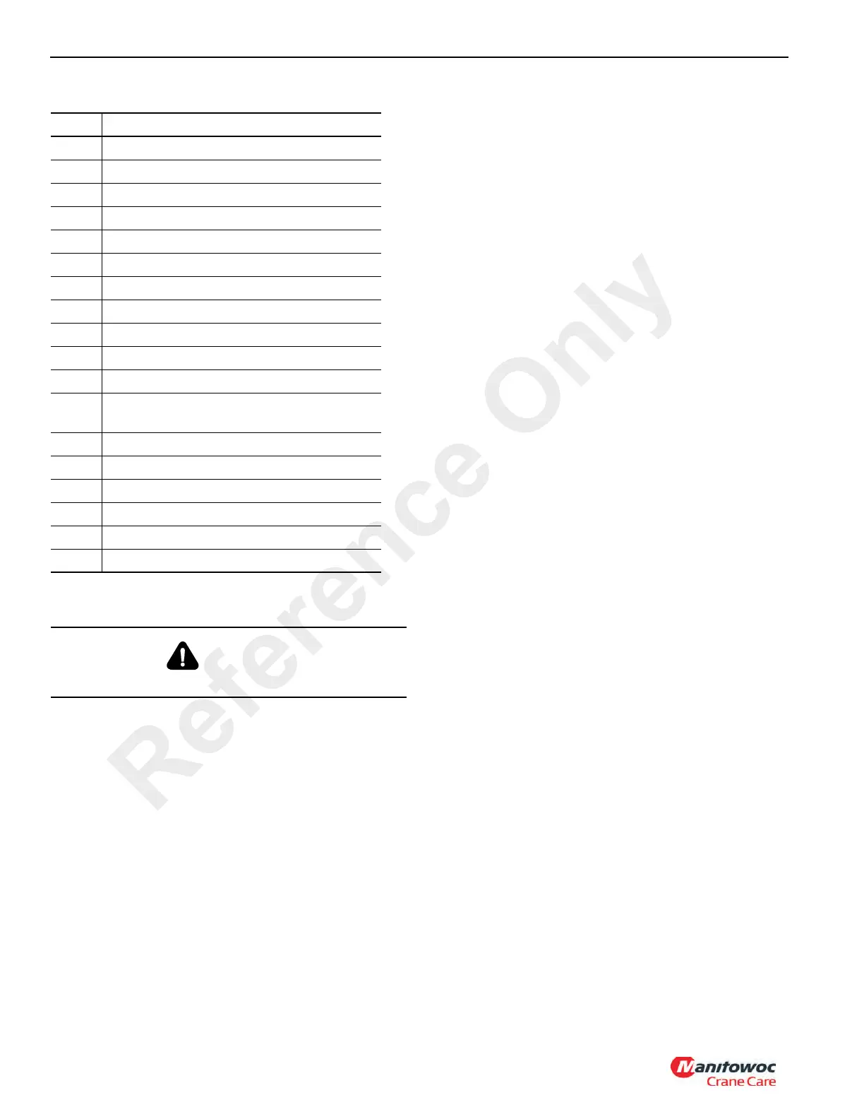
Item Description
1 Auxiliary Reservoirs
2 Cable Operated Drain Valve
3 Double Check Valve
4 Automatic Drain Valve
5 Air Dryer
6 Supply Dump Valve
7 Axle No. 1 Quick Release Valve
8 Spring Brake Control Valve
9 Pressure Protection Valve
10 Axle No. 2 Relay Valve
11 Primary Rear Service Reservoirs
12
Rear Axle (right Side Only) Park Brake Quick
Release Valve
13 Park Brake Relay Valve
14 Trailing Boom Tractor Protection Valve
15 Service Brake Relay Valve
16 Front Primary Supply Reservoir
17 Secondary Service Reservoirs
18 Air Governor
DANGER
Air pressure must not exceed 10.30 bar (150 psi).
Reference Only

 Loading...


