UNDERCARRIAGE TMS700E SERVICE MANUAL
8-32 Published 01-29-2015, Control # 512-01
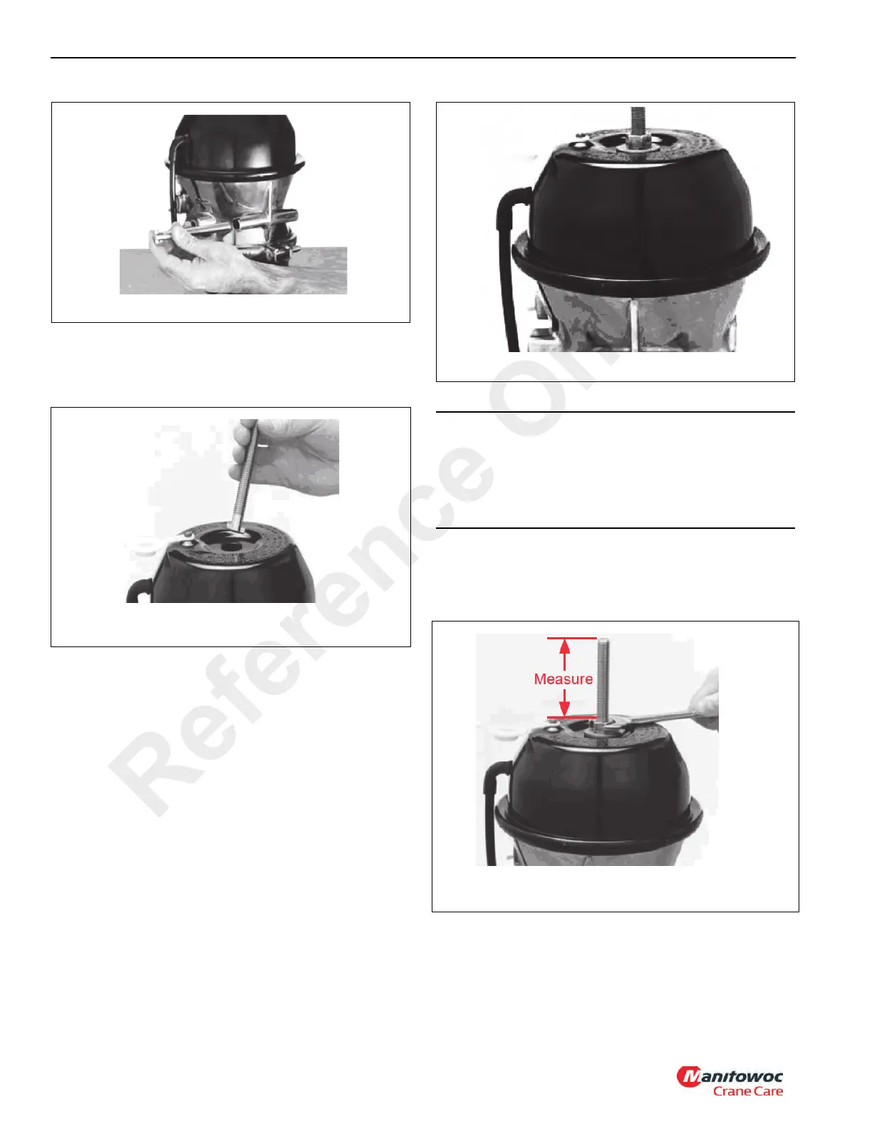
4. Insert the release-bolt into the center hole of the head.
Ensure the formed end of the bolt has entered the hole
in the piston inside the chamber. Continue to insert the
bolt until it bottoms out (Figure 8-28).
If not absolutely sure of correct bolt-to-piston engagement,
repeat step 5 until sure.
5. Turn the release-bolt 1/4 turn clockwise and pull the bolt
out to lock the formed end into the piston. If the bolt does
not lock into the piston in less than 1/2 inch outward
movement, repeat steps 4 and 5 until it locks.
6. Holding the bolt locked into the piston, install the
flatwasher and the release nut on the end of the release-
bolt, and turn down the nut against the flatwasher until
finger tight (Figure 8-29).
7. Using a 3/4 inch hand wrench turn the release-nut
clockwise until 8.2 cm (3.25 in) length of bolt extends
above the nut (Figure 8-30). Do not use an impact
wrench.
8. For easier manual-releasing, apply 6.20 - 8.61 bar (90 -
125 psi) air pressure to inlet port marked “SPRING
BRAKE” before step 4, but make sure to exhaust all air
pressure after step 7 and 8.
CAUTION
Do not exceed the length as stated in step 7. Do not
exceed 67.7 Nm (50 lb-ft) torque on release nut at any
time or damage may occur which could prevent any future
correct manual-releasing of the piggyback spring brake
chamber.
Reference Only

 Loading...


