Grove Published 01-29-2015, Control # 512-01 8-33
TMS700E SERVICE MANUAL UNDERCARRIAGE
9. To reactivate the piggyback/spring brake from its
manually-released position, reverse the order of steps 8
through 1.
10. When re-installing the release-bolt, flatwasher and
release-nut into the storage pocket, apply 13.5 Nm
(10 lb-ft) torque on nut against the flatwasher
(Figure 8-31).
11. Measure the distance from the center of the large clevis
to the air chamber mounting face with the brake fully
released. This is dimension “X” in (Figure 8-32).
12. Using a pry bar, move the slack adjuster so that the
linings contact the drum. Measure the distance between
the same points as in step 11. This dimension is “Y” in
Figure 8-32.
13. Subtract dimension “X” from dimension “Y”
(Figure 8-32). The difference should be 12.7 to 15.9 mm
(0.5 to 0.625 in). If the stroke falls within these limits, no
adjustment is required. If it falls outside these limits,
proceed to step 14 through step 16.
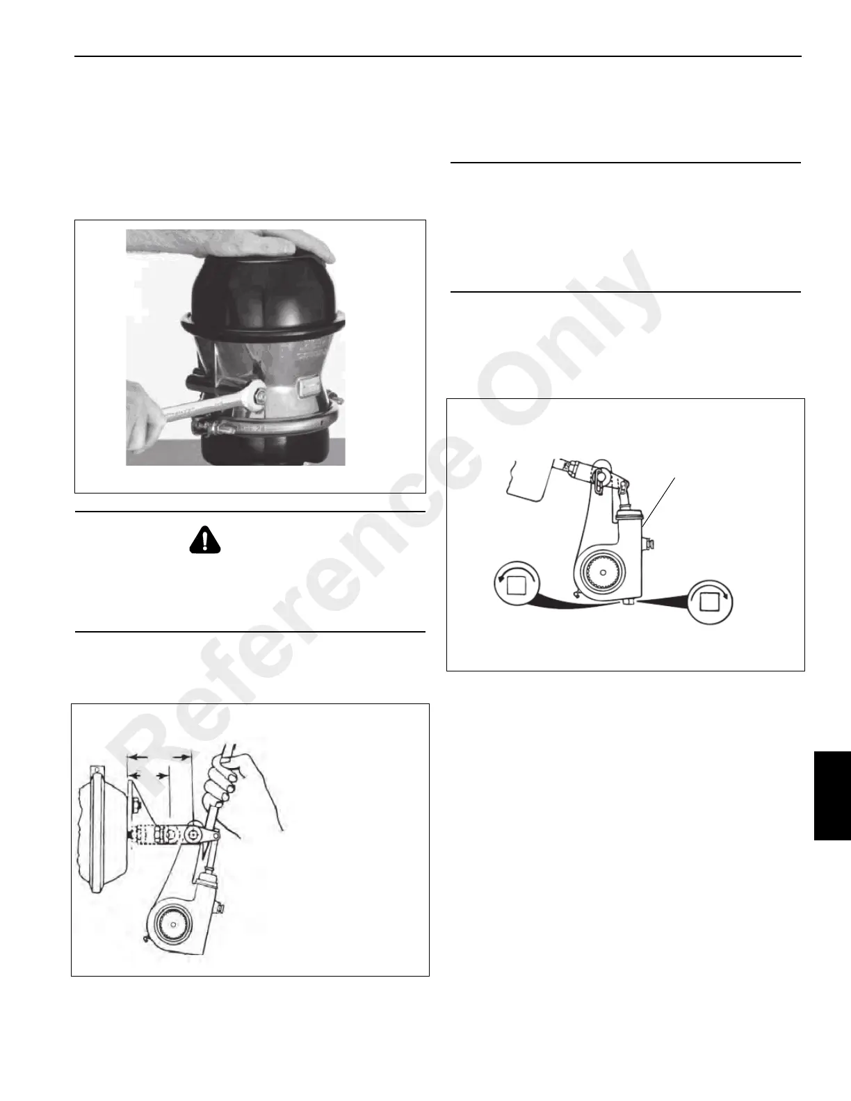
14. Disengage the pull pawl (Figure 8-33).
15. Turn the adjusting nut approximately 3.1 mm (0.1250 in)
turn in the direction required and re-measure the stroke.
Continue this process until the stroke is within limits
(Figure 8-33).
16. Release the pawl and uncage the spring brake, if
required.
DANGER
There are no serviceable parts inside the spring brake
chamber. Never attempt to disassemble the spring brake
chamber as serious personal injury could result from
accidental sudden release of the high energy spring.
MEASURE FREE STROKE
FREE STROKE = Y MINUS X
Drum brake free stroke must be
12.7 - 15.9 mm (0.5 - 0.625 in)
Disc brake free stroke must be
19.1 - 22.2 mm (0.75 - 0.875 in)
Y
X
7092-7
FIGURE 8-32
CAUTION
See Figure 8-32 and Figure 8-33, Free Stroke
Measurement. Pull pawl must be disengaged before
rotating adjusting nut. Pawl teeth will be damaged if not
disengaged. Pry on the pull pawl at least 0.8 mm
(0.0313 in) to disengage the teeth. When the pry bar is
removed, the pull pawl will re-engage immediately.
7092-8
Disengage a pull pawl
Shorten Stroke
Lengthen Stroke
FIGURE 8-33
Reference Only

 Loading...


