Grove Published 01-29-2015, Control # 512-01 3-7
TMS700E SERVICE MANUAL ELECTRIC SYSTEM
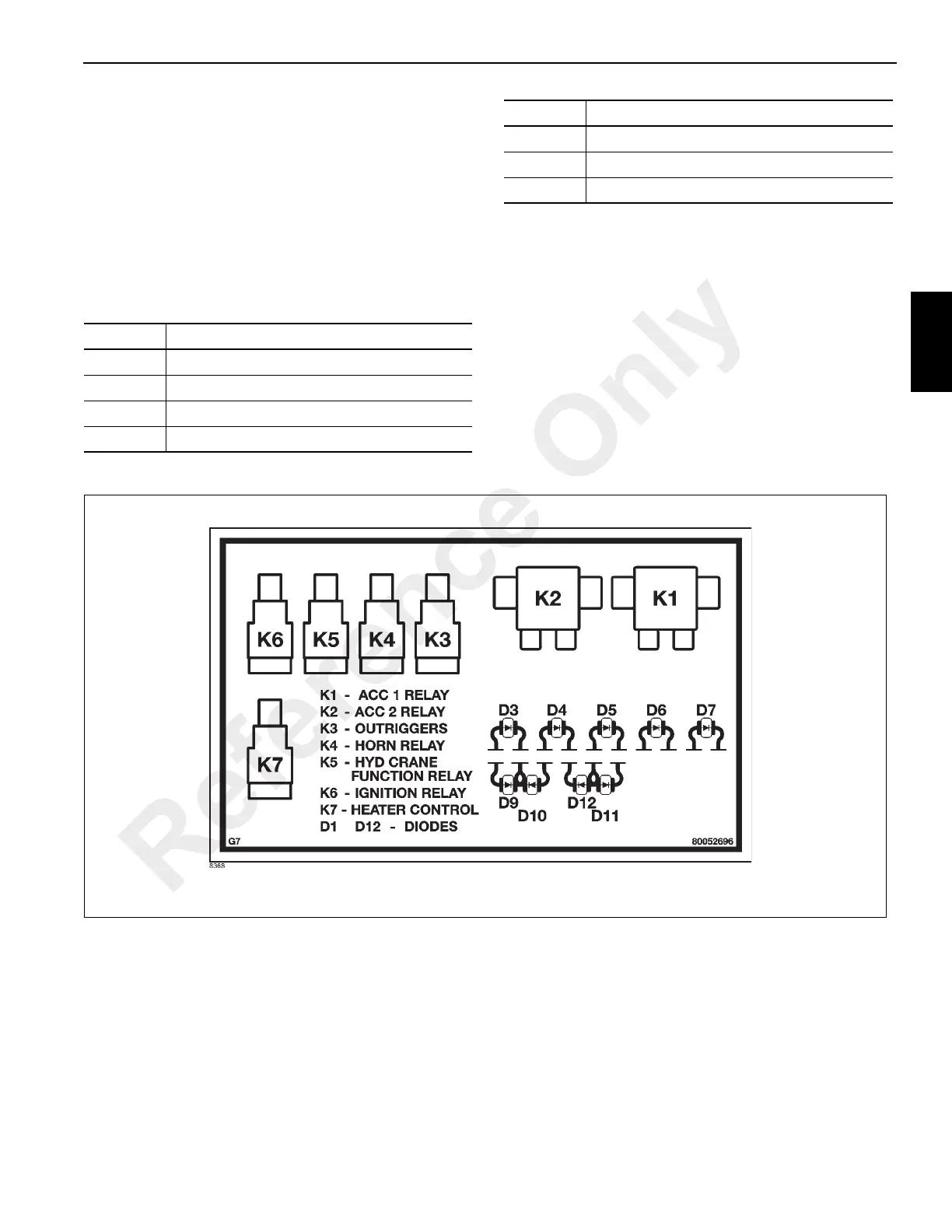
Relays
The superstructure has 7 relays (Table 3-4) (Figure 3-3 and
3-4) which control many of its functions. The relays are
located on the superstructure relay panel assembly
(Figure 3-4).
When any relay coil is energized, its contacts either close or
open. This allows power to go to or be removed from the
related circuits. For any relay coil to energize, the battery
must be connected.
Table 3-4
The coil of the accessory relays (K1 and K2) are energized
when the ignition switch is in the RUN (1) or ACC (3)
position.
The coil of the ignition relay (K6) is energized when the
carrier ignition switch is positioned to START (2) or ACC (3)
and held energized when ignition switch is released to RUN
(1). The coil of the swing horn relay (K4) is energized when
the swing horn button is depressed.
The coil of the crane function relay (K5) is energized when
the crane function switch is positioned to ON, the operator is
in the seat, and the left armrest is down.
Relay Relay Assignment
K1 ACC 1 Relay
K2 ACC 2 Relay
K3 Outriggers
K4 Horn
K5 Hyd Crane Function
K6 Ignition Relay
K7 Heater Control
Relay Relay Assignment
Reference Only

 Loading...


