Grove Published 01-29-2015, Control # 512-01 8-9
TMS700E SERVICE MANUAL UNDERCARRIAGE
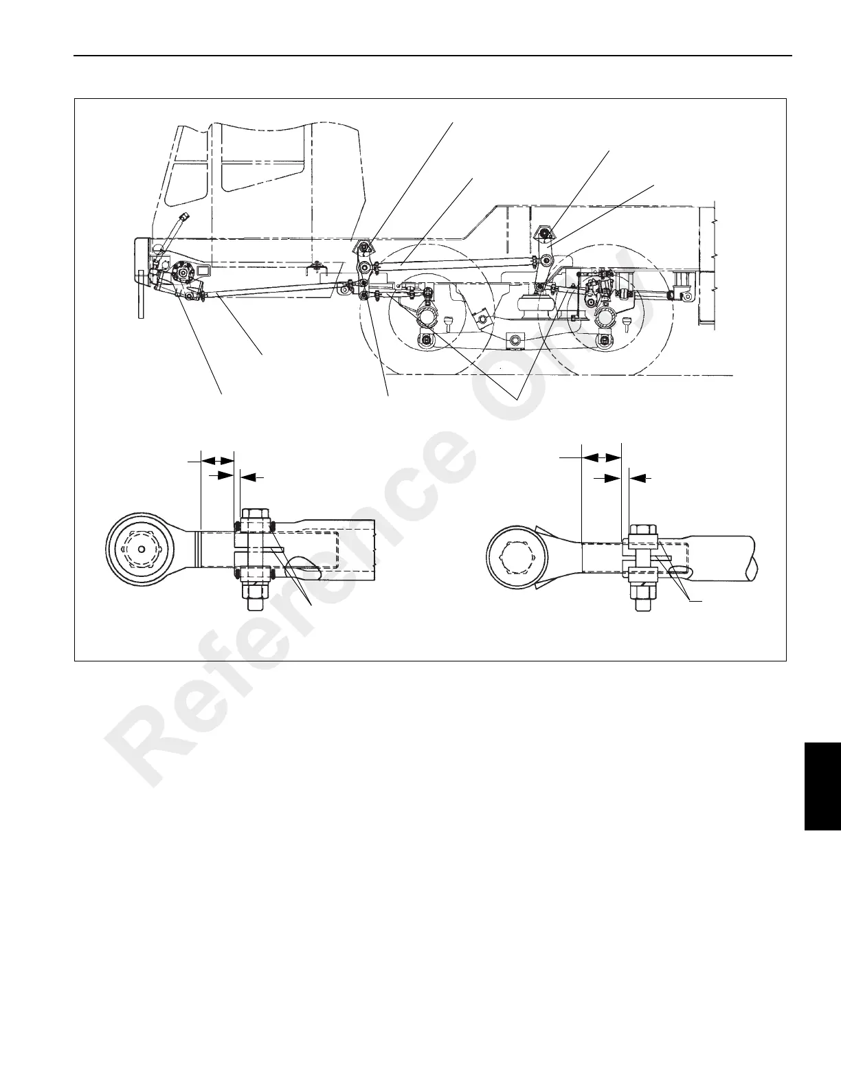
Setting Axle Stops and Steering Gear Relief Plungers
1. Start the engine and run at idle.
2. With the wheels on greased plates, turn the wheels in
both directions and check for clearances between all
moving parts. The clearances should be at least 1.00 in
(25 mm).
3. Adjust the axle stop as necessary to get the maximum
cramp angle and proper clearances.
4. Put the full weight of the machine on properly inflated
tires and on a hard firm surface.
35.6 mm (1.40 in)
Max. Exposed
Threads Allowed
6.4 mm (0.25 in)
6.4 mm (0.25 in)
43.4 mm (1.71 in)
Max. Exposed
Threads Allowed
Align Clamp With
Slot In Tube
Align Clamp with
Slot in Tube
Drag Links (Detail #5)
Drag Link
(Detail #6)
Drag Link
(Detail #7)
Drag Link (Detail #7)
Drag Links (Detail #5 & #6)
Steering
Gearbox
Front Relay Arm
(Detail #9)
Rear Relay Arm
(Detail #8)
Rear Relay Arm
Rig Pin
Front Relay Arm
Rig Pin
FIGURE 8-5
Reference Only

 Loading...


