Grove Published 01-29-2015, Control # 512-01 8-39
TMS700E SERVICE MANUAL UNDERCARRIAGE
Spring Brake Actuator
The upper part of the brake air chamber containing the large
spring is not serviceable; however, the lower part of the
assembly is serviceable.
1. Remove the caging bolt and washer from its storage
hole on the outside of the brake chamber.
2. Remove the dust cap from the bolt hole in the top of the
chamber.
3. Insert the head of the caging bolt through the opening
and turn bolt 1/4 turn clockwise.
4. Thread the nut and washer on the bolt and turn the nut
clockwise about 18 to 21 turns. Air pressure can be
applied to the spring brake chamber through the parking
port to compress the spring while the nut is being
tightened.
5. Do not force the nut beyond its normal stop. A torque of
40.6 Nm (30 lb-ft) is the maximum that should be
required. Reverse the procedure to uncage the spring.
Removal
1. Cage the spring brake.
2. Tag, remove, and cap the air lines to the brake air
chamber.
3. Remove the pin(s) connecting the clevis to the slack
adjuster.
4. Mark the position of the clevis on push rod so that the
clevis can be reinstalled in the same position.
5. Brake is dragging. a. Low spring brake hold-off air
pressure, 70 psi (482 kPa).
a. Check for minimum spring
brake pressure, 4.82 bar (70
psi). Check for proper
functioning of air system
components.
b. Improper connection of the
service line at spring brake.
b. Check and connect line to
proper port.
c. Leaking lines or spring brake
seals.
c. Tighten connections on air
lines or replace spring brake
unit seals.
Symptom Probable Cause Solution
WARNING
Spring brake unit is powerful enough to cause parts to fly
apart with enough force to cause personal injury. The
spring brake must be caged before removing or servicing
brakes before returning the crane to service.
DANGER
Cage the spring brake before removal of air brake
chamber.
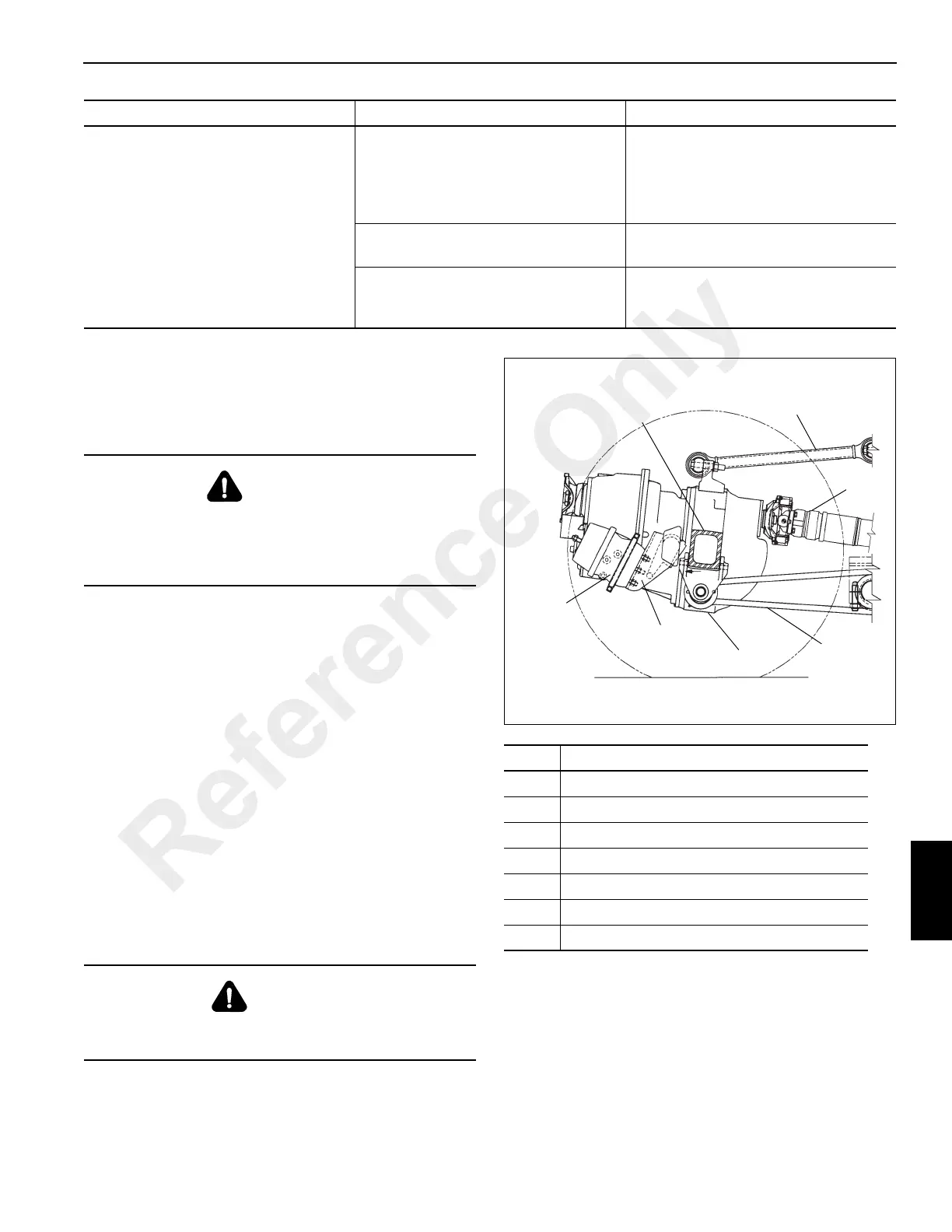
Item Description
1 Brake Air Chamber
2 Axle No. 3
3 Torque Rod
4 Drive Shaft
5 Stabilizer Beam
6 Differential
7 Mounting Bracket
Reference Only

 Loading...


