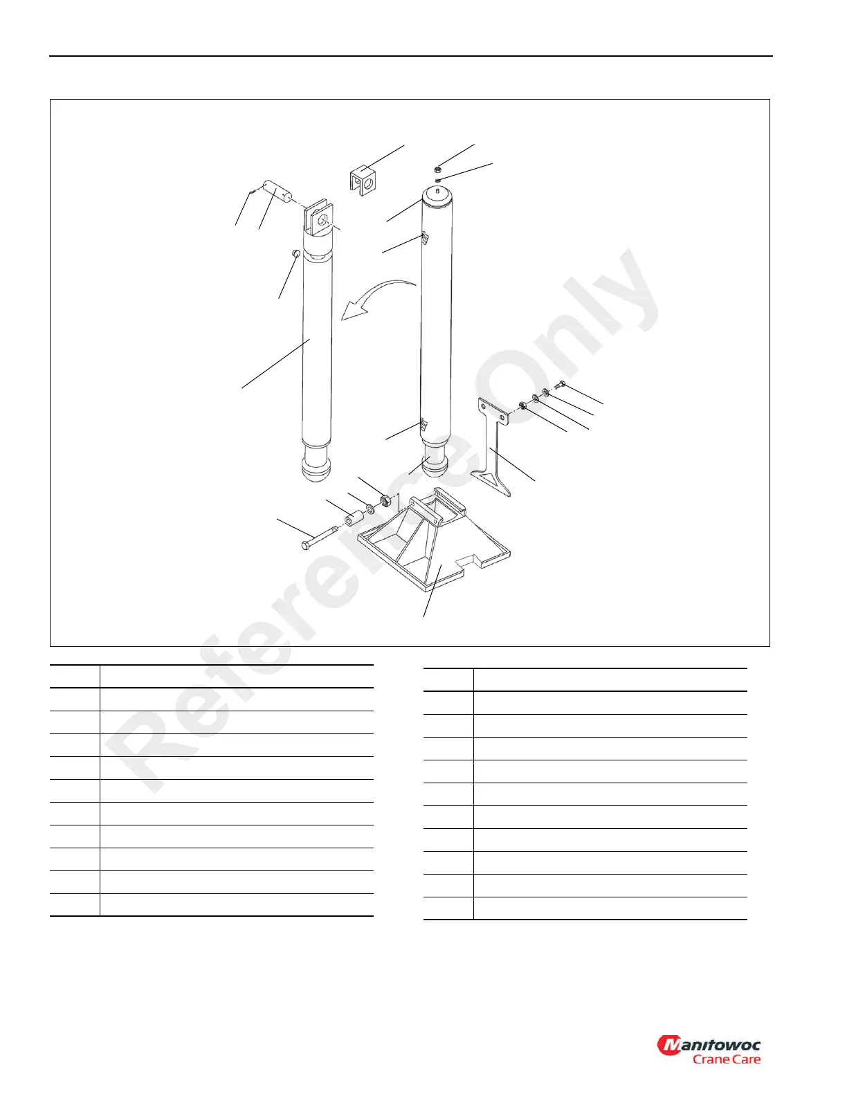
EasyManuals Logo

Manitowoc Grove TMS700E User Manual

Manitowoc Grove TMS700E
352 pages
To Next Page IconTo Next Page
To Previous Page IconTo Previous Page
Page #326 background imageLoading...
Page #326 background image
UNDERCARRIAGE TMS700E SERVICE MANUAL
8-74 Published 01-29-2015, Control # 512-01
17
3
FIGURE 8-71
18
19
2
8
5
20
7
4
10
13
11
12
9
15
16
14
6
6512
1
Welded tube shown with cylinder inside
and with cylinder tube cap outside
fastened to cap bracket inside. Wear
rings are shown inside because they
keep cylinder and tube from making
metal-to-metal contact. Cylinder rod end
is on top and barrel end is on bottom.
1
Item Description
1 Jack Cylinder
2 Cotter Pins
3 Cylinder Retaining Pin
4 Cylinder Head Wear Ring
5 Piston Wear Ring
6 Jack Pad (Float Pad)
7 Bushing
8Hex Nut
9 Lockwasher
10 Tilt Plate
Item Description
11 Capscrew
12 Flatwasher
13 Plug
14 Capscrew
15 Locknut
16 Flatwasher
17 Cylinder Tube Cap
18 Washer
19 Acorn Nut
20 Cap Bracket
Reference Only

Table of Contents

Questions and Answers:

Question and Answer IconNeed help?

Do you have a question about the Manitowoc Grove TMS700E and is the answer not in the manual?

Manitowoc Grove TMS700E Specifications

General IconGeneral
BrandManitowoc
ModelGrove TMS700E
CategoryConstruction Equipment
LanguageEnglish

Related product manuals