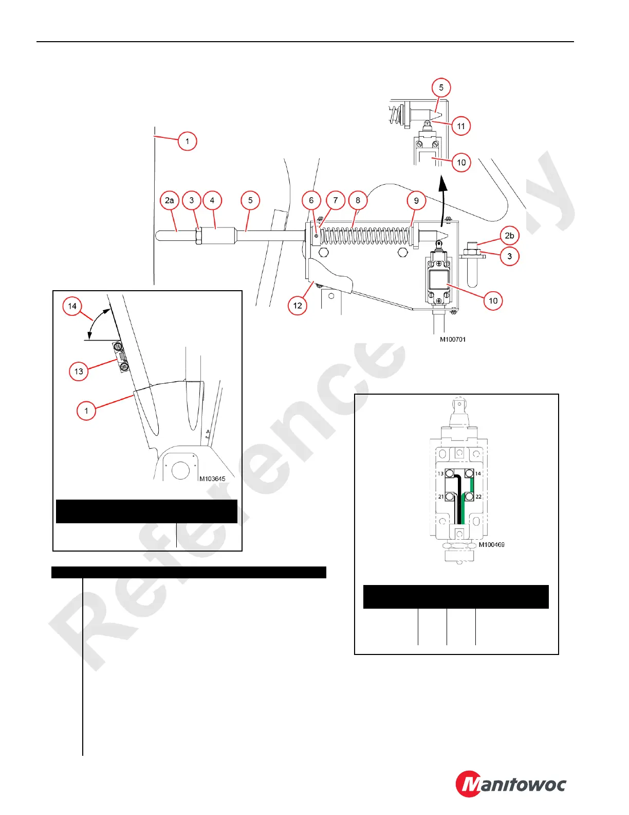
Item Description
1 Boom Butt
2a Adjusting Rod for Boom without Luffing Jib: 7-3/4 in (197 mm)
2b Adjusting Rod for Boom with Luffing Jib: 3-11/32 in (85 mm)
3Jam Nut
4 Coupling (welded to actuator rod)
5Actuator Rod
6 Spring Pin
7 Spring Washer
8Spring
9 Spring Washer
10 Limit Switch
11 Over-Travel—Switch Opened
12 Cover
13 Digital Protractor-Level
14 Digital Level Angle
View D Limit Switch Wiring
Wire Color
Switch
Terminals
Function
Green 14 22 Maximum Angle
Black 13 Ground
White 21 24 VDC Supply
View C Left Side of Boom Butt
Maximum Boom Angle
Digital Level
Angle (14)
82.7° Boom without Luffing Jib 74.34°
88.0° Boom with Luffing Jib 79.64°
View A
SWITCH OPENED
Figure 4-2
View B
SWITCH OPENED
STORED
 Loading...


