Manitowoc Published 05-26-17, Control # 238-02 10-7
MLC165-1 SERVICE/MAINTENANCE MANUAL ACCESSORIES
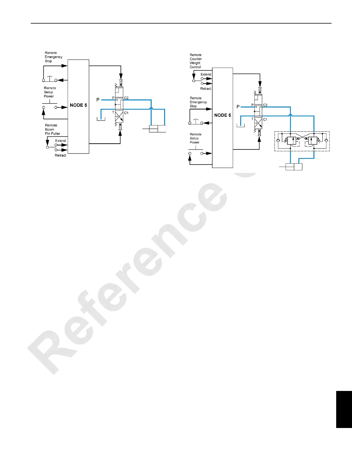
Boom Butt Pin Pullers
Neutral
Node 1 sends 24Vdc to the boom pins disengage switch pole
in cab. Node 5 sends 24Vdc to the boom hinge pins engage/
disengage switch in the remote set up controller. The
switches are momentary and normally open, so the
corresponding node reads 0Vdc back when no switches are
being pressed.
Engage
When the boom hinge pins engage/disengage switch in the
remote set up controller is toggled to the engage position,
the engage contact closes and sends the 24Vdc supply
signal back to node 5. Node 5 then sends a 24Vdc signal to
the boom hinge pins out solenoid, energizing it.
The valve spool moves to the open position. Fluid flows from
the pressure port, through the valve, and on to the cylinder.
As fluid fills the barrel end of the cylinder, the rod extends
and the movement forces fluid out of the rod end, through the
open holding valve, through the open valve, and back to
tank.
Disengage
When the boom hinge pins engage/disengage switch in the
remote set up controller or cab is toggled to the disengage
position, the disengage contact closes and sends the 24Vdc
supply signal back to the corresponding node. Node 5 then
sends a 24Vdc signal to the boom hinge pins in solenoid,
energizing it.
The valve spool moves to the reversing position. Fluid flows
from the pressure port, through the valve, and on to the
cylinder. As fluid fills the rod end of the cylinder, the rod
retracts and the movement forces fluid out of the barrel end,
through the open holding valve, through the open valve, and
back to tank.
Counterweight Cylinders
Neutral
Node 5 sends 24Vdc to the left and right counterweight raise/
lower switches in the remote set up controller. The switches
are momentary and normally open, so the corresponding
node reads 0Vdc back when no switches are being pressed.
Node 5 drives no solenoids in this state, so the valve spool is
centered by the return springs in the neutral position. The
center valve position is closed, so no fluid flows to the
cylinder. The holding valves are also in the closed position,
so no fluid can flow from the rod or barrel end of the cylinder
if a load on the cylinder is producing pressure.
Raise
When the left or right counterweight cylinder raise/lower
switch is toggled to the raise position, the raise contact
closes and sends the 24Vdc supply signal back to node 5.
Node 5 then sends a 24Vdc signal to the left or right
counterweight up solenoid, energizing it.
The valve spool moves to the open position. Fluid flows from
the pressure port, through the valve, and on to the holding
valve. At the holding valve, fluid flows through the check
valve at the barrel end of the valve and into the barrel end of
the cylinder. At the same time, fluid opens the valve at the
rod end of the cylinder. As fluid fills the barrel end of the
cylinder, the rod extends and the movement forces fluid out
of the rod end, through the open holding valve, through the
open valve, and back to tank.
Lower
When the left or right counterweight cylinder raise/lower
switch is toggled to the lower position, the lower contact
closes and sends the 24Vdc supply signal back to node 5.
M100839
Figure 10-8. Boom Butt Pin Puller Control
M100843
Figure 10-9. Counterweight Cylinder Control
 Loading...


