Manitowoc Published 05-26-17, Control # 238-02 6-7
MLC165-1 SERVICE/MAINTENANCE MANUAL SWING SYSTEM
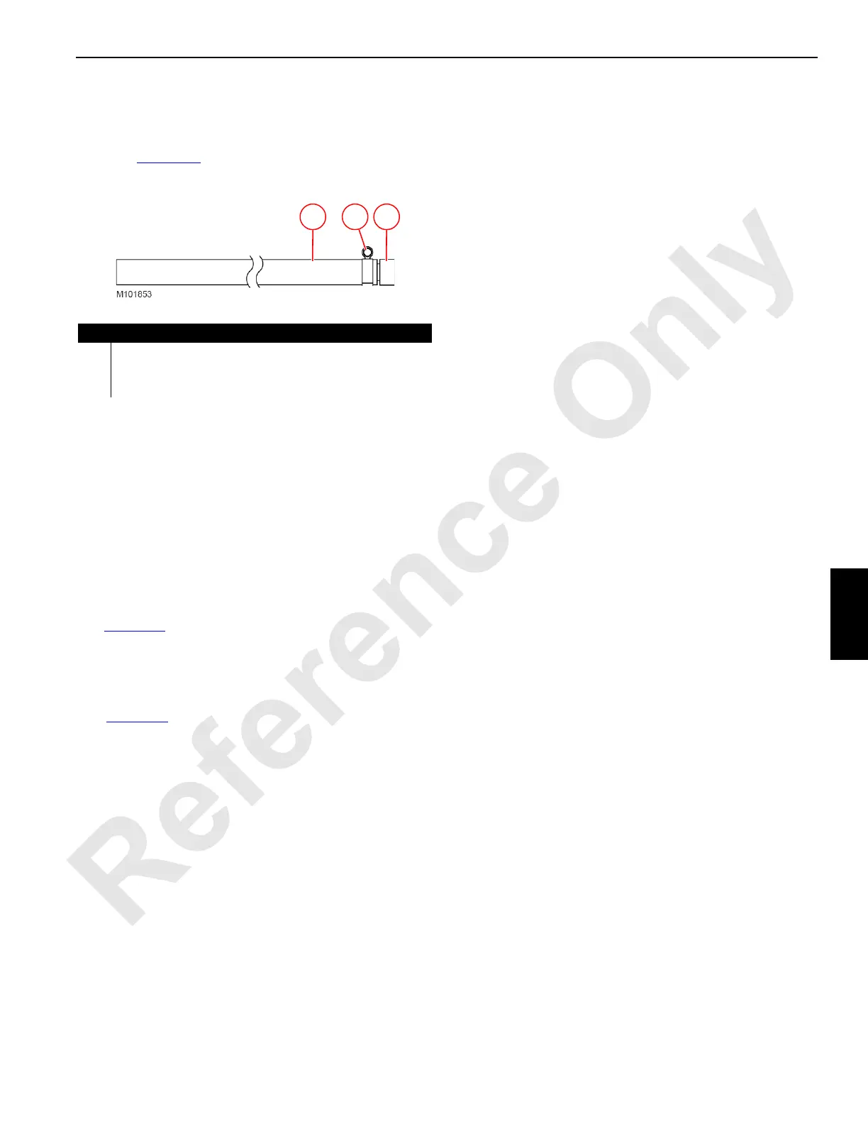
Quick-Drain Valve
The swing gearbox is equipped with a quick-drain valve
which requires use of the quick-drain drainer assembly
shown in Figure 6-5
. The quick-drain drainer assembly is
stored in the parts box supplied with the crane.
Oil Change Procedure
The oil change interval may be adjusted according to the
results of an oil analysis program.
Change the oil when the gearbox is warm, not hot.
NOTE To prevent harmful contaminants from entering the
gearbox, thoroughly clean components before
disconnecting or connecting them.
See Figure 6-4
for the following procedure.
1. Lock out/tag out the crane.
2. Remove the dust cap (4) from the quick-drain valve (5).
3. Place the hose from the quick-drain drainer assembly
(Figure 6-5
) into a suitable container for collecting the
drained oil: 2 gallons (7,5 L) of oil is required to fill a dry
gearbox.
4. Thread the quick-drain drainer assembly all the way
onto the quick-drain valve (5). The poppet inside the
valve will open, allowing the oil to drain from the
gearbox.
5. Once the gearbox has finished draining, remove the
quick-drain drainer assembly.
6. Fasten the dust cap (4) to the quick-drain valve (5).
7. Fill the gearbox with specified oil:
MANUAL FILL PROCEDURE (very slow process)
a. Remove the breather (2) from the fill port (3).
b. Add oil through the fill port (3) using a suitable
funnel until the oil level is halfway up the sight glass
(1). Do not overfill.
c. Reinstall the breather (2) in the fill port (3).
POWER FILL PROCEDURE (recommended)
a. Remove the dust cap (4) from the quick-drain valve
(5).
b. Thoroughly clean the inside of the hose for the
quick-drain drainer assembly.
c. Thread the quick-drain drainer assembly all the way
onto the quick-drain valve (5). The poppet inside the
valve will open.
d. Connect the hose from the quick-drain drainer
assembly to a portable pump, either hydraulically
powered or hand powered.
e. Slowly pump oil into the gearbox until the oil level is
halfway up the sight glass (1). Do not overfill.
f. Once the gearbox is filled, remove the quick-drain
drainer assembly.
g. Fasten the dust cap (4) to the quick-drain valve (5).
8. Recheck the oil level after operating the swing drive. If
necessary, add oil through the fill port (3).
9. Thoroughly clean the quick-drain drainer assembly and
store it in the parts box.
Figure 6-5. Quick-Drain Drainer Assembly
Item Description
1 Quick-Drain Drainer
2 Hose Clamp
3 Hose: 3/4 in (19 mm) Inside Diameter by 10 ft (3,0 m) Long
123
 Loading...


