Manitowoc Published 05-26-17, Control # 238-02 5-1
MLC165-1 SERVICE/MAINTENANCE MANUAL HOISTS
SECTION 5
HOISTS
HOIST THEORY OF OPERATION
This section will discuss the electrical and hydraulic control
of the crane hoists. For details on individual components,
some are covered later in this section and others are
covered in Section 2 Hydraulics and Section 3 Electrical.
NOTE For a description of the overall crane hydraulic
system and additional free fall details on the
components described in this section, refer to
Section 2.
Overview of the Hoist System
Also see Figure 5-2 on page 5-2.
Each hoist system (drum 1, 2, 3, and 4) is comprised of
essentially identical control circuits and components. The
main differences between the hoists are:
• Drum 1 and 2 use identical motors. See Drum 1 and
Drum 2 Motor on page 5-5.
• Drum 3 and 4 use identical motors. See Drum 3 and
Drum 4 Motor on page 5-7.
• The control software governs the operational
characteristics differently for each hoist.
• A free fall option is available for hoists 1 and 2. See Free
Fall System (Optional) on page 5-8.
The hydraulic system for each hoist motor is comprised of a
high-volume, high-pressure circuit and a low-pressure pilot
circuit. The high-pressure, high-volume flow is supplied by
the double main pump. The pilot system is supplied by the
charge pump.
The main pump generates two flows to the control valve
manifold. The two flows can remain separate within the
manifold or they can be shared by use of the Drum Speed
switch. See Flow Sharing
on page 5-1.
For each hoist, the pilot system consists of two hydraulic
circuits which originate at the control handle in the operator
cab: an up circuit and a down circuit. Both pilot circuits
terminate at a directional control valve that is proportional
and is located on the control valve manifold.
Depending on how the directional control valve is
commanded by the control handle (by way of the pilot
system), the valve routes high pressure working flow to the A
port or the B port of the hoist motor.
Flow Sharing
NOTE The hoist motors are on an open-loop system fed
by the double main pump. This means that the
hoist motor speed can be affected by the
simultaneous operation of other crane equipment.
See Section 2 for more information on the open
loop system.
At times it may be desirable to combine the two flows from
the main pump. This can be done through the use of the
Drum Speed switch. When the switch is moved to the high
speed position, it energizes a solenoid valve located in the
control valve manifold. The solenoid valve shifts an on-off
valve which connects the load sense and working pressure
flows within the two halves of the control valve manifold.
With the Drum Speed switch in the closed position (high
speed), both of the main pump flows feed all hoist and travel
motors. In the open position (low speed), each flow
separately supplies two hoist motors and one travel motor.
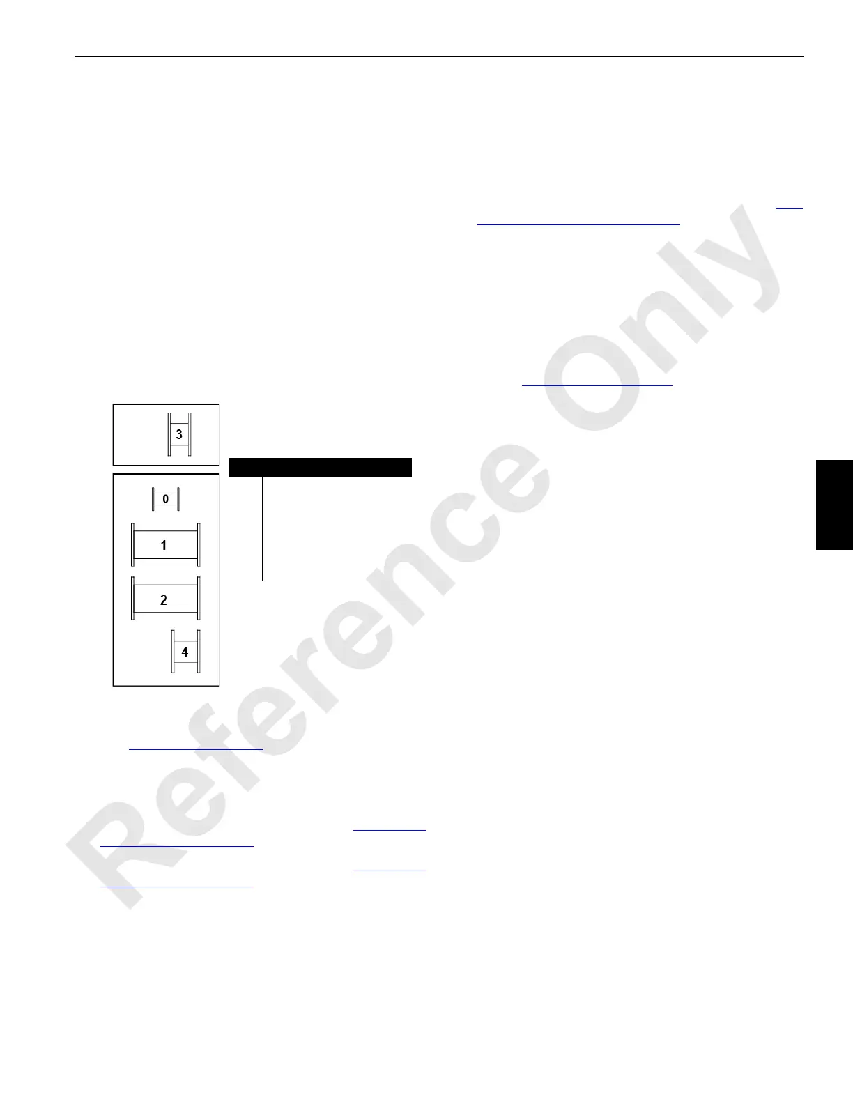
Item Description
0 Rigging Winch
1 Front Load Drum
2 Rear Load Drum
3 Auxiliary Load Drum or
Luffing Hoist (in boom butt)
4 Boom Hoist
Front of Crane
Figure 5-1. Drum Number Designations
M101099

 Loading...


