Manitowoc Published 05-26-17, Control # 238-02 3-15
MLC165-1 SERVICE/MAINTENANCE MANUAL ELECTRICAL SYSTEM
Checking Electrical Inputs/Outputs (Using
the Test Box)
Troubleshoot components on the main display, system
diagnostic screen first. Perform additional testing with the
Electrical Test Kit at universal nodes or Manitowoc Unit
Tester at all nodes. The Electrical Test Kit or Manitowoc Unit
Tester can be ordered from your Manitowoc dealer.
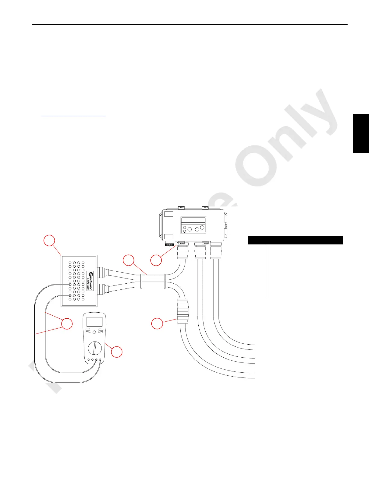
The breakout test kit provides a breakout of the node signals
to easily probed bayonet connections. Each node connector
(2) Figure 3-19 on page 3-15
is keyed uniquely and requires
a matching keyed test harness assembly (4) from the
Electrical Test Kit.
The output terminals of the electrical test box (3) are labeled
A1 through 40V, corresponding to node connector (2) pin
numbers. Both a number and letter are included in each
designator because some systems number the pin
connections and others letter the connections. Use either the
numbers or letters as they apply to your system.
I/O node and pin numbers are contained in the Test Volt
tables.
To probe a fault at a universal node with the Electrical Test
Kit:
1. Shutdown the engine and turn the engine key switch to
off.
2. Determine which signal contains the suspected fault.
3. Disconnect the node cable (1) from the node connector
(2) containing the signal of the suspected fault.
4. Connect the electrical test box (3) and test harness (4)
between the node connector (2) and disconnected node
cable (1).
5. Turn the engine key switch to on and activate the
suspected fault.
6. Use a multimeter (5) and bayonet test probes (6) to
probe signals at the test box (3) as needed in
conjunction with toggling node outputs.
.
Figure 3-19. Test Box Setup
M100782
6
3
4
5
1
2
Item Description
1 Node Cable
2 Node Connector
3 Breakout Box
4 CAN Bus W3, W4, or W6 Test
Harness
5 Multimeter
6 Bayonet Test Probes

 Loading...


