Manitowoc Published 05-26-17, Control # 238-02 5-33
MLC165-1 SERVICE/MAINTENANCE MANUAL HOISTS
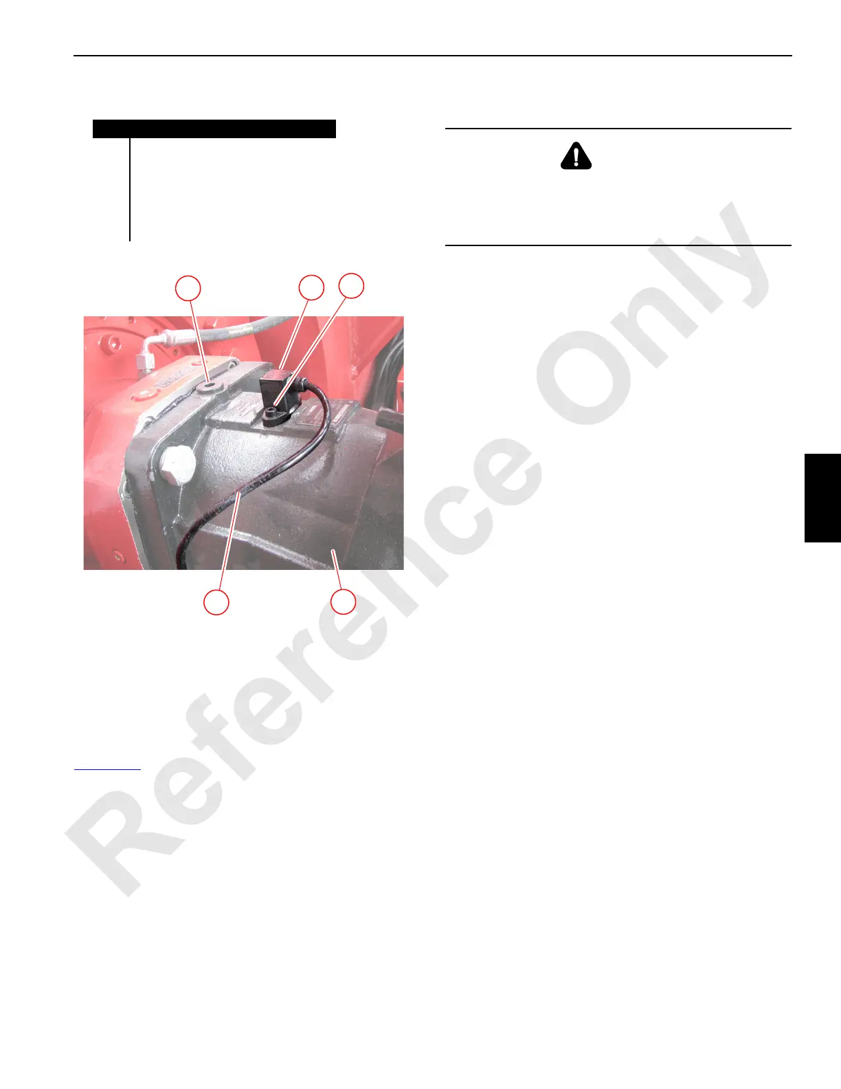
SPEED SENSOR—HOIST MOTORS
Figure 5-24
A speed sensor (1) is installed in each non-free fall hoist
motor. The sensor sends rotational speed and direction
information to the master controller to be used by the crane
control functions.
There is no adjustment for the speed sensor.
Replacement
1. Stop the engine and wait for the hydraulic oil to cool.
2. Disconnect the sensor cable (4) from the wire harness.
3. Thoroughly clean all around the sensor to prevent dirt
from entering the hydraulic system.
4. On motors positioned so that the sensor is on the
underside of the motor, place a suitable container under
the drain plug (5) and remove the drain plug.
5. Remove the two sensor mounting screws (2).
6. Remove the faulty sensor (1) with O-ring. Be careful to
contain any hydraulic fluid that might drain from the
motor.
7. Clean the mating surfaces, then install a new sensor and
O-ring.
8. Install the mounting screws to the correct torque value
for the size screw.
9. Re-connect the sensor cable to the wire harness.
10. On motors positioned so that the sensor is on the
underside of the motor:
a. Make sure that the drain plug is clean, then install
the drain plug.
b. Thoroughly clean all around the fill plug, then
remove the fill plug.
c. Fill the motor with filtered hydraulic oil of the proper
type.
d. Make sure that the fill plug is clean, then re-install
the fill plug.
11. Start the engine and operate the hoist.
12. Check for a steady drum speed (rpm) and direction
signal on the corresponding drum’s information display
in cab.
13. Make sure there is no leakage.
Figure 5-24. Motor Speed Sensor
Item Description
1 Speed Sensor (with O-ring)
2Screw (2)
3Hoist Motor
4Sensor Cable
5 Drain Plug (when motor is positioned
with sensor underneath)
1
3
2
4
M100746
5
WARNING
Burn Hazard
Oil will drain from the port when the sensor is removed.
Wait for the hydraulic oil to cool before removing the
sensor.
 Loading...


