Manitowoc Published 05-26-17, Control # 238-02 3-9
MLC165-1 SERVICE/MAINTENANCE MANUAL ELECTRICAL SYSTEM
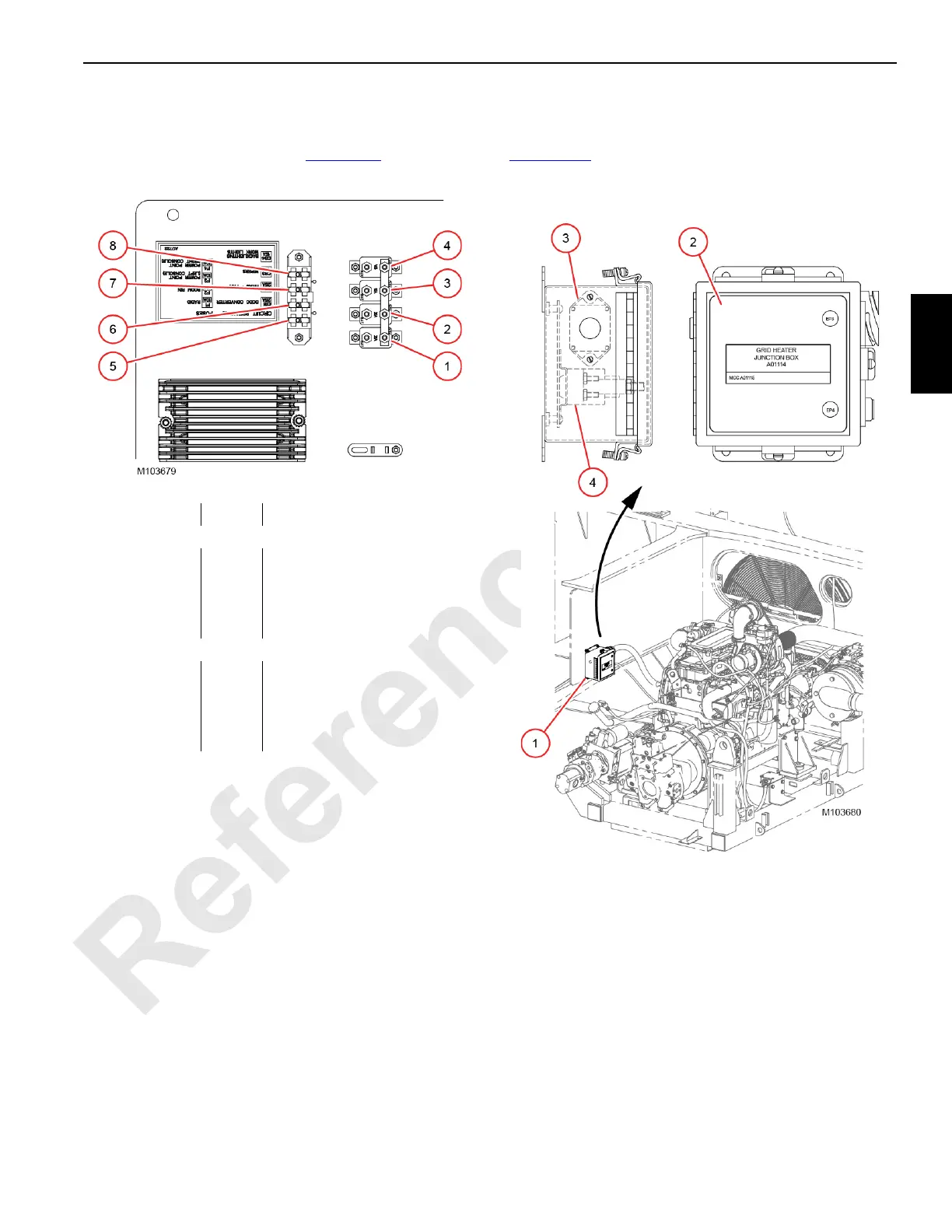
operator cab
Four circuit breakers and four fuses are mounted in the rear
console behind the operator seat (Figure 3-13
).
Grid Heater
For the Tier 3 engine, a 120 amp circuit breaker (3)
(Figure 3-14
) and one high power relay contactor (4) is
located in the grid heater junction box (1) mounted in the left-
front side of the engine compartment.
Figure 3-13. operator cab Circuit Breakers
Item Amps Description
Circuit Breakers
1 CB-1 25 DC Converter
2 CB-2 25 Air Conditioning/Heater Fan
3 CB-3 15 Front and Overhead Wiper
4 CB-4 15 Back Lighting / Work Lights
Fuses
5 F1 10 Radio
6 F2 10 Boom RIN
7 F3 10 Power Point (Left Console)
8 F4 10 Power Point (Right Console)
Figure 3-14. Grid Heater Junction Box
Item Description
1 Grid Heater Junction Box
2 Junction Box Cover
3 120 amp Circuit Breaker
4 100 amp Contactor Relay
 Loading...


