ELECTRICAL SYSTEM MLC165-1 SERVICE/MAINTENANCE MANUAL
3-4
Published 05-26-17, Control # 238-02
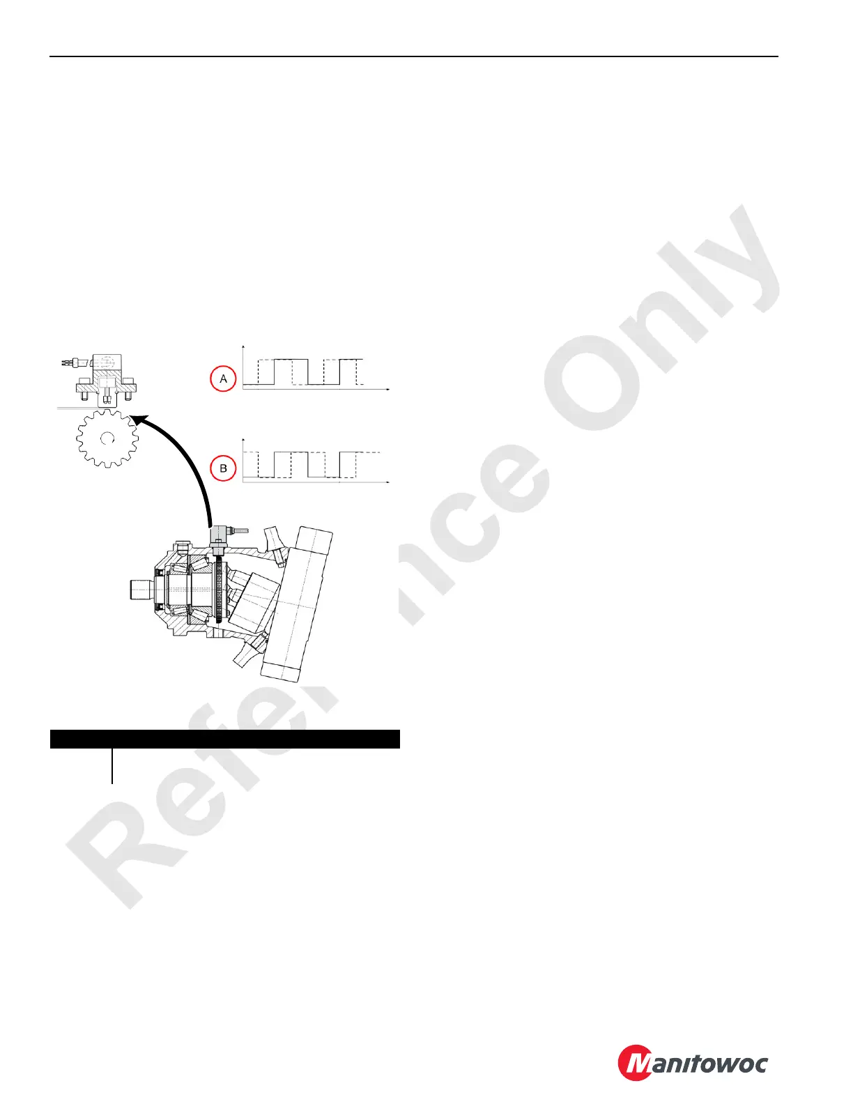
Motor Speed Sensors
A universal node provides power to Hall-effect speed
sensors within the hydraulic motors that drive the drums and
rotational bed. A gear wheel within the motor has teeth that
move past the speed sensor as a motor shaft spins, causing
the sensor to produce two square-wave signals that are
offset with a 90° phase delay.
The frequency of the square waves is determined by the
number of teeth on the circumference of the gear wheel and
shaft speed. The rotational direction is determined by which
signals phase leads the other. Software uses the square-
wave frequency and phase information to calculate the
rotational speed and direction of the motor.
Drum Free Fall Sensors
Universal node 5 provides power to an incremental encoder
within the free fall sensors of Drum 1 and 2. As drum rotation
causes the encoder shaft to rotate, the encoder produces
two square-wave signals that are offset with a 90° phase
delay.
The number of pulses produced is proportional to the
amount of shaft rotation. The rotational direction is
determined by which signals phase leads the other. Software
then uses the pulse count and phase information to calculate
drum position and rotational direction.
Limit Switches — Single Contact
In the non-tripped state, a universal node provides power to
the normally closed contact. The universal node reads the
applied power back through the normally closed contact as a
logic high. When the switch is tripped, the normally closed
contact opens, breaking the path of power through the
common terminal. The universal reads this as a logic low.
Limit Switches — Dual Contact
In the non-tripped state, a universal node provides power to
the normally closed contact and grounds the normally open
contact. The universal node reads the applied power through
the normally closed contact back through the common
center terminal as a logic high. When the switch is tripped,
the normally closed contact opens, breaking the path of
power through the common terminal. At the same time, the
normally open contact closes, grounding the common
terminal and sending the universal l node a logic low signal.
Limit switches are used to sense the travel limits of:
• Swing limit
• Drum 1 and 2 minimum bail limits
• Maximum boom angle
• Boom and luffing jib upper and lower block up limits
• Minimum and maximum luffing jib angles
Solenoids
Solenoids activate hydraulic valves and provide control of:
• Boom raise and hinge pin cylinders
• Brake cylinders
• Counterweight cylinders and pins
• Cab tilt cylinders
• Assembly cylinder
• Drum motors
• Swing motor
• Handle Selects
• Horse power over-ride
• Load sense shifting
• Travel pilot
• Pilot pressure unloading
• Cooler fan pump
• Proportional pressure control
• Free fall enables
• Auto grease control
Item Description
A Clockwise Rotation Signals
B Counter-Clockwise Rotation Signals
Figure 3-7. Motor Speed Sensor
M100821

 Loading...


