EasyManuals Logo
Home>Manitowoc>Construction Equipment>MLC165-1

Manitowoc MLC165-1 Service Maintenance Manual

Manitowoc MLC165-1
246 pages
To Next Page IconTo Next Page
To Previous Page IconTo Previous Page
Page #64 background imageLoading...
Page #64 background image
Reference Only
ELECTRICAL SYSTEM MLC165-1 SERVICE/MAINTENANCE MANUAL
3-2
Published 05-26-17, Control # 238-02
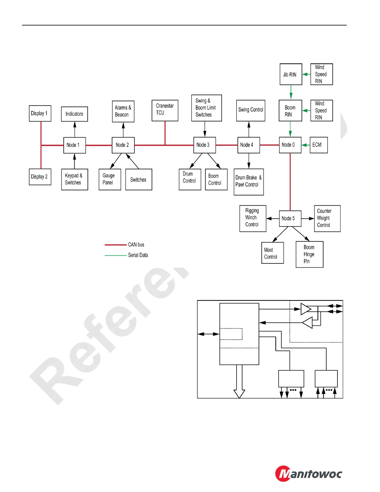
Master Node (Node 1)
The microprocessor within the master node executes the
main control program for crane operation and contains
memory for lookup information such as load charts. Digital
inputs and outputs communicate with low current digital
devices within the cab such as keypads, indicators, and
control switches.
Figure 3-2. CAN Bus Major Functions
M100791
Figure 3-3. Master Node
M100792
RS-232
Display Output
Digital
Inputs
Digital
Outputs
CAN Bus
Transceiver
Micro-
processor

Table of Contents

Other manuals for Manitowoc MLC165-1

Questions and Answers:

Question and Answer IconNeed help?

Do you have a question about the Manitowoc MLC165-1 and is the answer not in the manual?

Manitowoc MLC165-1 Specifications

General IconGeneral
BrandManitowoc
ModelMLC165-1
CategoryConstruction Equipment
LanguageEnglish

Related product manuals