HYDRAULIC SYSTEM MLC165-1 SERVICE/MAINTENANCE MANUAL
2-10
Published 05-26-17, Control # 238-02
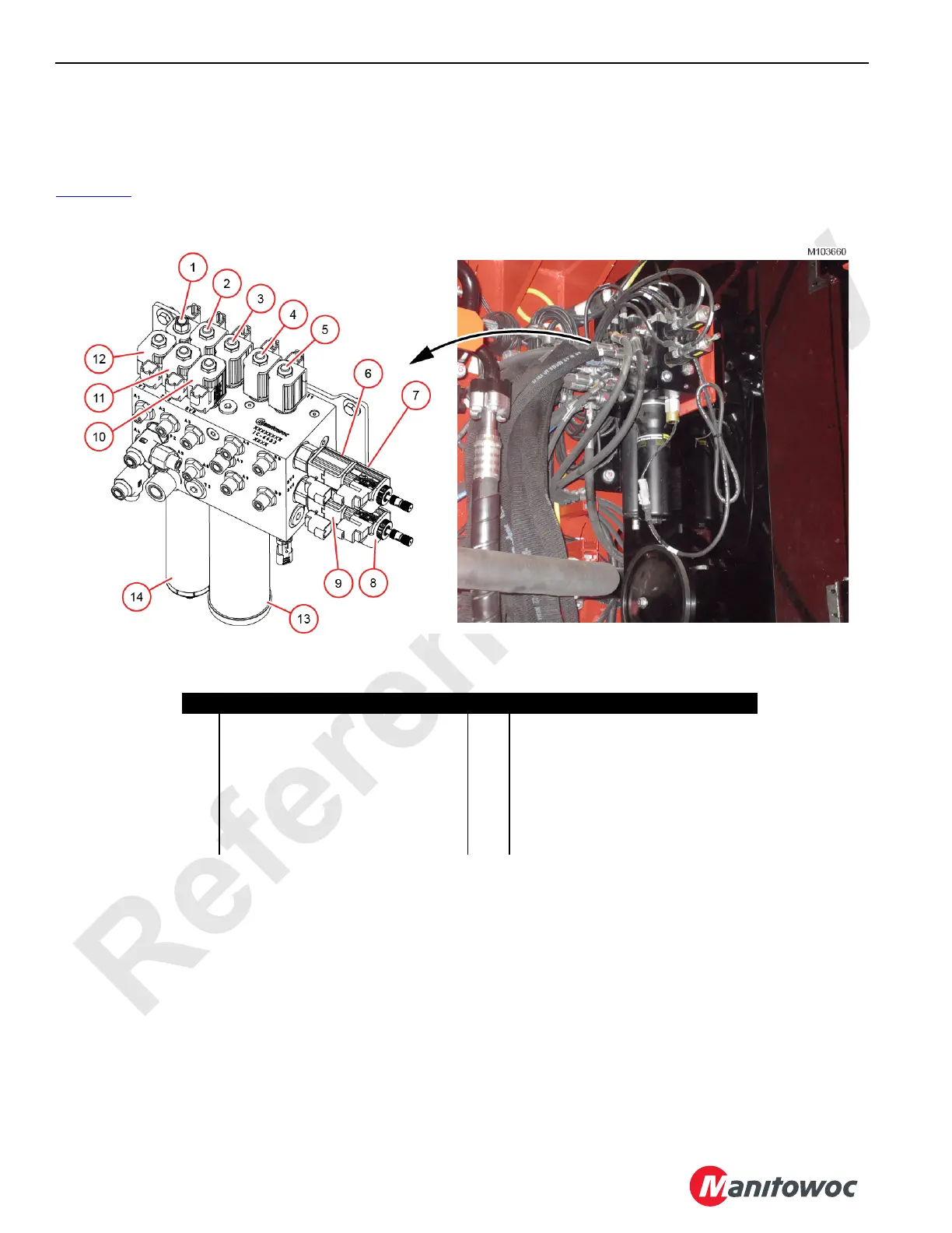
Pilot Brake and Pawl Manifold
The pilot brake and pawl manifold receives flow from the
charge pump within the main pump. Solenoid valves in the
manifold control flow to the brake and pawl functions listed in
Figure 2-13
.
Item Description Item Description
1 Travel Pilot 8 Drum 1 Pawl Disengage (front drum)
2 Travel Hi-Speed 9 Drum 1 Pawl Engage (front drum)
3 Drum 4 Brake (boom hoist) 10 Drum 1 Brake (front drum)
4 Drum 3 Brake (aux drum) 11 Drum 2 Brake (rear drum)
5 Pilot Pressure Unloading 12 Swing Brake
6 Drum 4 Pawl Engage (boom hoist) 13 Filter
7 Drum 4 Pawl Disengage (boom hoist) 14 Accumulator
Figure 2-13. Pilot Brake and Pawl Manifold
Left-Side Enclosure on Hydraulic Tank
 Loading...


