Manitowoc Published 05-26-17, Control # 238-02 3-27
MLC165-1 SERVICE/MAINTENANCE MANUAL ELECTRICAL SYSTEM
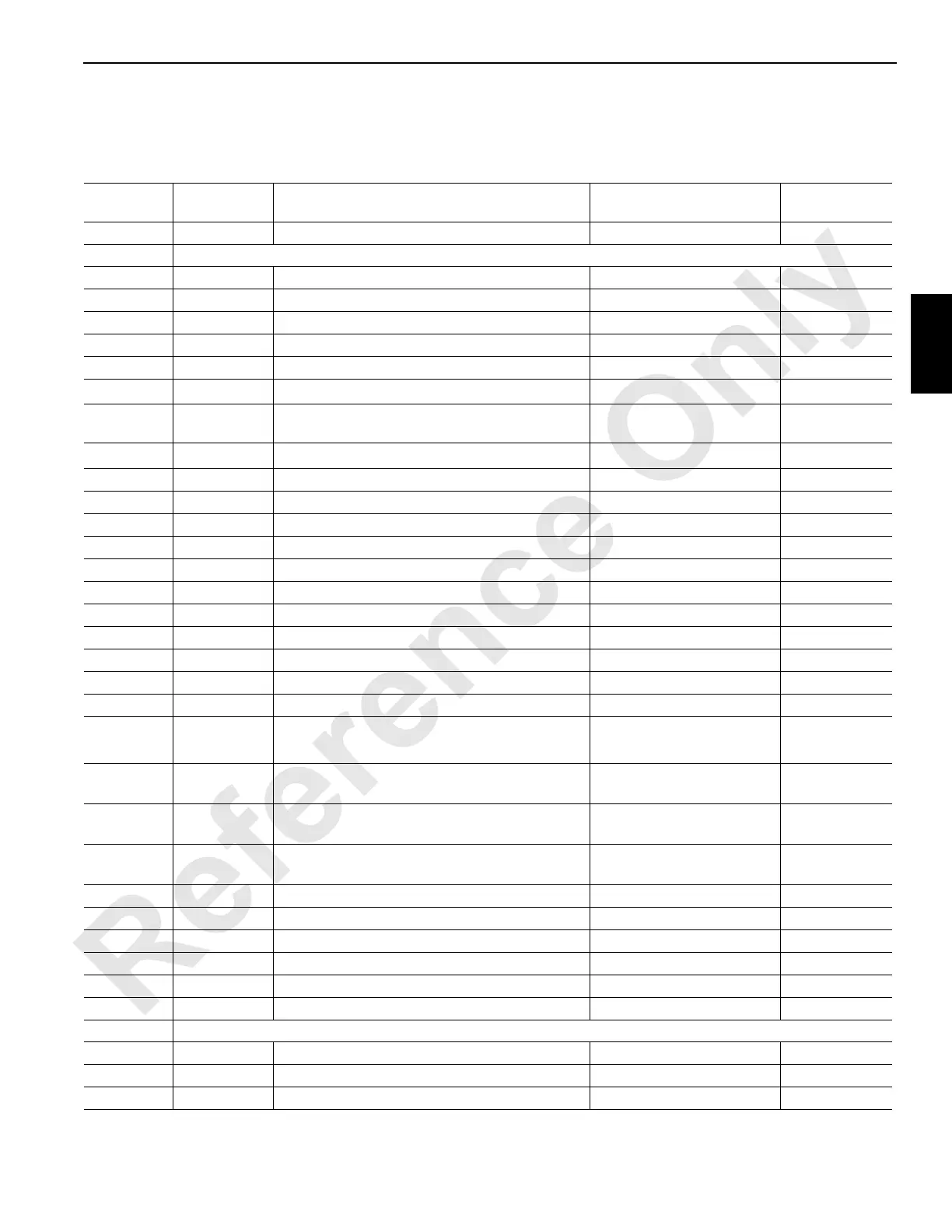
Node 5 — Accessories
See Electrical Schematic 81019880, Sheets 13, 14, 20, and 22 (at end of this section).
Receptacle
Number
Function
Type
Description Test Voltages
CAN Packet
Number
J1-WN10
I/O Cable — From Engine Node N/A
J3/W53 Receptacle – Accessories
53-A Ground Right Side Swing Travel Alarm
Ground
53-B DO-1 Right Side Swing Travel Alarm
0 Volts Off; 24 Volts On
CAN24-1-1
53-C Ground Accessory Pump Pressure Control HS-502
Ground
53-D DO-2 Accessory Pump Pressure Control HS-502
0 Volts Off; 24 Volts On
CAN24-1-2
53-E Ground Node Select 4 Jumper to Ground
Ground
53-F DO-3 Accessory Pump Displacement Control HS-503
0 Volts Off; 24 Volts On
CAN49-6
1
53-G Ground
Cooler Fan Pump Controls HS-504 and
Accessory Pump Displacement Control HS-503
Ground
53-H DO-4 Cooler Fan Pump Controls HS-504
0 Volts Off; 24 Volts On
CAN49-8
1
53-J Ground Drum 1/Drum 2 Minimum Bail Limit Switch
Ground
53-N Ground Rigging Winch Pay In/Out
Ground
53-P DO-5 Rigging Winch Pay Out HS-505
0 Volts Off; 24 Volts On
CAN24-1-16
53-R DO-6 Rigging Winch Pay In HS-506
0 Volts Off; 24 Volts On
CAN24-1-32
53-S NS-4 Node Select 4 Jumper to Ground
0 Volts (With Jumper)
53-T DI-3 Drum 1 Minimum Bail Limit Switch
0 Volts Off; 24 Volts On
CAN44-1-4
53-U 24 Volts Drum 1 Minimum Bail Limit Switch
24 Volts Nominal
53-V 24 Volts Drum 2 Minimum Bail Limit Switch
24 Volts Nominal
53-W DI-4 Drum 2 Minimum Bail Limit Switch
0 Volts Off; 24 Volts On
CAN44-1-8
53-X 24 Volts Accessory Pressure Sensor
24 Volts Nominal
53-Z 24 Volts Engine Fuel Level Sensor
24 Volts Nominal
53-a AI-1 Engine Fuel Level Sensor
1 Volt Empty
9 Volts Full
CAN16-2
1
53-b AI-2 Load Pin Right
2mA (no load) to 20mA
(50,000 KGs)
CAN16-4
1
53-c AI-3 Cooler Fan Pressure Sensor
1 Volt at 0 psi,
5 Volts at 7,000 psi
CAN16-6
1
53-d AI-4 Accessory Pressure Sensor
1 Volt at 0 psi,
5 Volts at 7,000 psi
CAN16-8
1
53-g Ground Engine Fuel Level Sensor
Ground
53-h Ground Accessory Pressure Sensor
Ground
53-k Ground Cooler Fan Pressure Sensor
Ground
53-m Ground Load Pin Right
Ground
53-n 24 Volts Load Pin Right
24 Volts Nominal
53-s 24 Volts Cooler Fan Pressure Sensor
24 Volts Nominal
J4/W54 Receptacle – Accessory Pressure, Fuel Level Sensor, Left Load Pin, Rigging Winch
54-A Ground Counterweight Pins In HS-511
Ground
54-B DO-11 Counterweight Pins In HS-511
0 Volts Off; 24 Volts On
CAN24-2-4
54-C Ground Counterweight Pins Out HS-512
Ground
 Loading...


