Manitowoc Published 05-26-17, Control # 238-02 2-9
MLC165-1 SERVICE/MAINTENANCE MANUAL HYDRAULIC SYSTEM
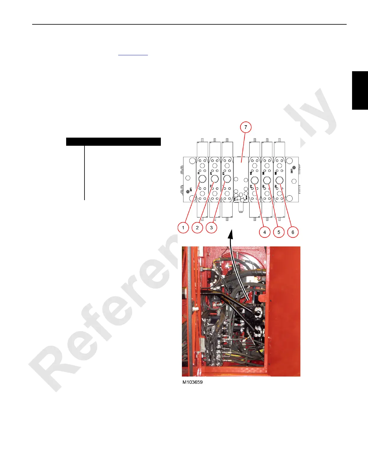
Main Control Valve Manifold
The main control valve manifold (Figure 2-12) controls flow
to the drum and travel motors. Each rotary group of the main
pump generates flow to the main control valve manifold.
At times it may be desirable to combine the two flows. This
can be done with the Drum 1/2 high speed switch in the cab.
When the switch is moved to the high speed position, node 3
energizes solenoid valve HS-302 located in the control valve
manifold. The solenoid valve shifts an on-off valve which
connects the load sense and working pressure flows within
the two halves of the control valve manifold.
When the high speed switch is in the on position, both of the
main pump flows feed all drum and travel motors. In the off
position, each flow separately supplies two drum motors and
one travel motor.
Item Description
1 Drum 3 (aux/luffing drum)
2 Drum 2 (rear load drum)
3 Right Travel
4 Left Travel
5 Drum 4 (boom hoist)
6 Drum 1 (front load drum)
7 Combined Flow
Figure 2-12. Main Control Valve
Left-Side Enclosure
 Loading...


