Manitowoc Published 05-26-17, Control # 238-02 3-1
MLC165-1 SERVICE/MAINTENANCE MANUAL ELECTRICAL SYSTEM
SECTION 3
ELECTRICAL SYSTEM
DRUM IDENTIFICATION
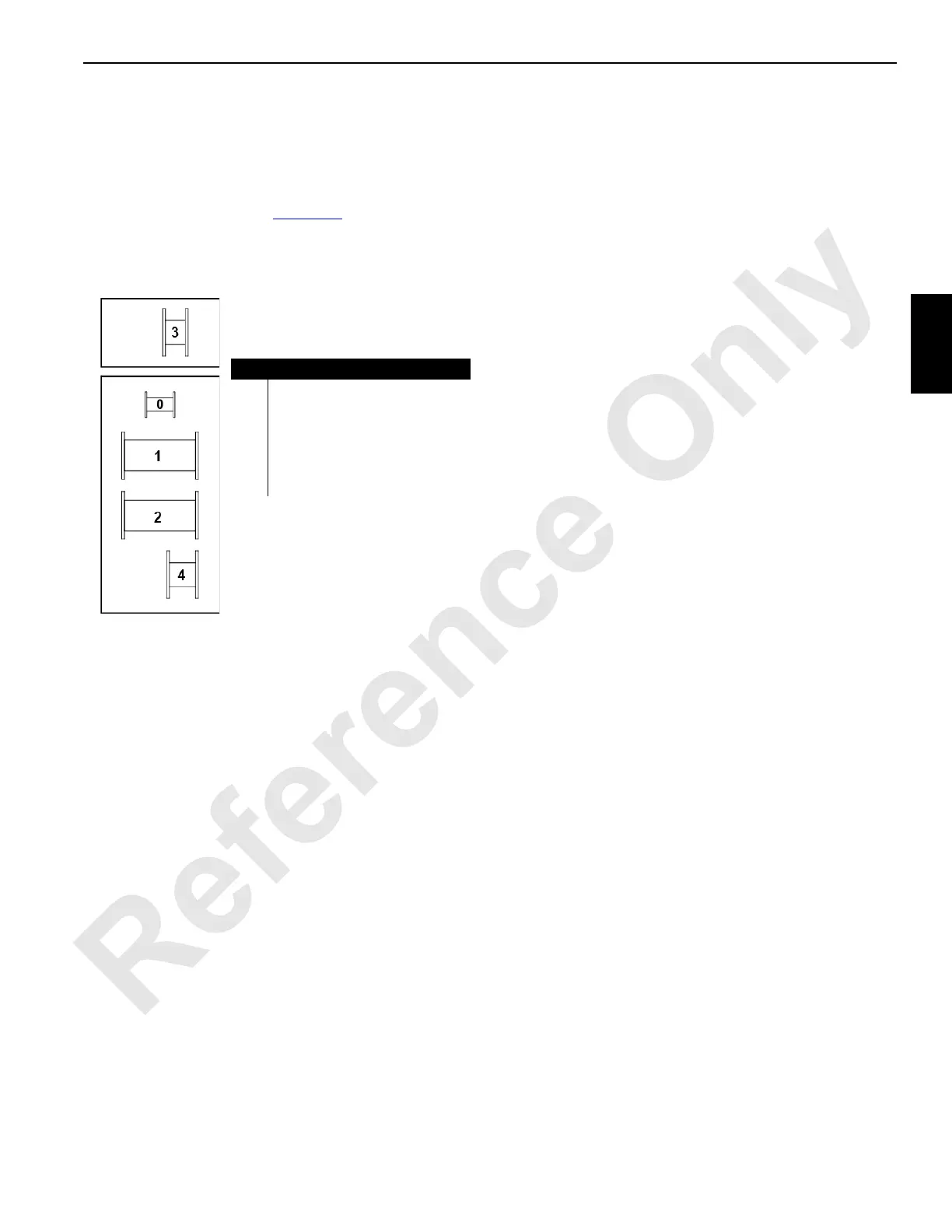
The drum numbers given in Figure 3-1 are used to identify
the drums in this section.
ELECTRICAL POWER SEQUENCE
Engine Bus Power
The batteries provide power through the battery disconnect
switch. When the switch is open, battery power is only
available to the grid heater. When the switch is closed,
battery power becomes available to the circuits powered by
the engine bus:
• Engine start and run switch
• Starter solenoid
• Engine Electronic Control Module (ECM)
• A/C circuit
• Horns
• Dome light
Cab Bus Power
With the battery switch closed and engine bus power
available, placing the ignition switch in the run position
closes the cab power relay in node 0, providing power to the
circuits on the cab bus:
• A/C and heater
• Wiper motors
• Panel lights
• Work lights
• Monitor
• Overhead console
• Engine Node 0
A DC to DC converter on the cab bus converts the 24Vdc
cab bus voltage to 12Vdc for use by boom power and the
radio.
CAN Bus Power
Engine Node 0 receives power from the cab bus and passes
that power to the controller area network bus (CAN Bus)
relay in node 0. The CAN Bus relay closes, providing power
to the remaining CAN Bus nodes, as well as the boom and
luffing jib remote input nodes (RIN).
CAN BUS CONTROL SYSTEM
CAN is a multi-master broadcast serial bus standard for
connecting nodes. Each node is able to send and receive
messages, but not simultaneously. A message consists
primarily of an ID, which represents the priority of the
message, and up to eight data bytes. It is transmitted serially
onto a two wire differential bus.
CAN uses priority based bus arbitration. If the bus is free,
any node may begin to transmit. If two or more nodes begin
sending messages at the same time, the message with the
higher priority ID sends its message, which is received by all
nodes.
A transceiver within each node translates voltage and
current levels between the microprocessor and the
differential bus. When receiving, it converts signal levels
from the bus to levels that the microprocessor uses. When
transmitting, it converts signals from microprocessor level to
the bus level.
Several types of node controllers are used with functionality
that matches the type of devices they are controlling and
communicating with.
Item Description
0 Rigging Winch
1 Front Load Drum (whip hoist)
2 Rear Load Drum (main hoist)
3 Auxiliary Load Drum or Luffing
Hoist (in boom butt)
4Boom Hoist
Front of Crane
Figure 3-1. Drum Identification
M101099

 Loading...


