ELECTRICAL SYSTEM MLC165-1 SERVICE/MAINTENANCE MANUAL
3-8
Published 05-26-17, Control # 238-02
CIRCUIT BREAKERS
Alternator Circuit
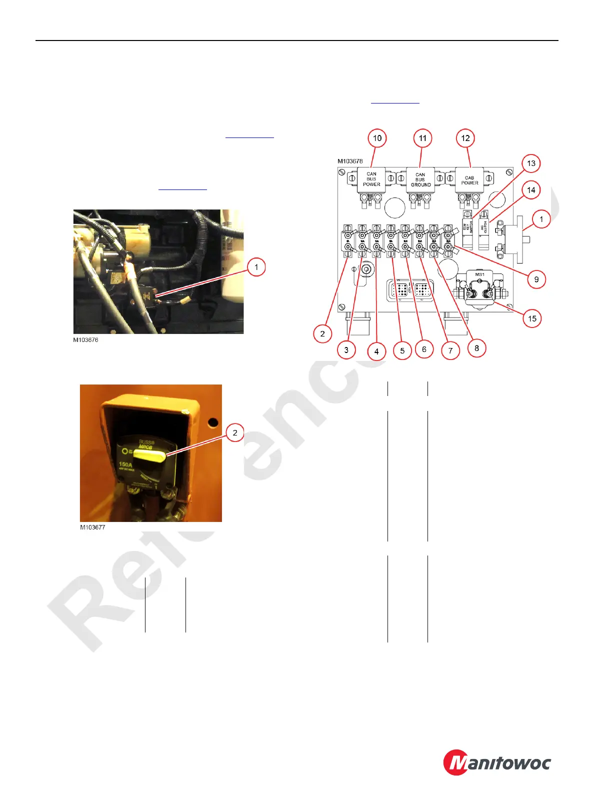
For the Tier 3 engine, a 120-amp circuit breaker (CB-0) is in
the circuit between the alternator and the starter. The circuit
breaker is located next to the starter (View A, Figure 3-11
).
For the Tier4 engine, a 150-amp circuit breaker (CB-0) is in
the circuit between the alternator and the batteries. The
circuit breaker is located on the rear of the battery box in the
right-side enclosure (View B, Figure 3-11
).
Engine Node
Circuit breakers CB-1 through CB-9 are mounted in the
engine node 0 (Figure 3-12
).
Item
Circuit
Breaker
Amps Description
1 CB-0 120 Tier 3 Engine
2 CB-0 150 Tier 4 Engine
Figure 3-11. Alternator Circuit Breaker
View A
At Starter on Rear of Engine
View B
Right Enclosure on Battery Box
Figure 3-12. Engine Node Circuit Breakers
Item Amps Description
Circuit Breaker
1 CB-1 60 Main System 24 V Power
2 CB-2 8 ECM Key Switch
3 CB-3 10 Cummins Diagnostics
4 CB-4 10 Key Switch
5 CB-5 15 Air Compressor Clutch
6 CB-6 30 Cummins ECM
7 CB-7 30 Starter Solenoid
8 CB-8 50 CAN-Bus Power
9 CB-9 50 Cab Power
Relays
10 — 50 CAN-Bus Power
11 — 50 CAN-Bus Ground
12 — 50 Cab Power
13 — 10 ECM Key Switch
14 — 10 Air Compressor Clutch
15 MS1 50 Starter Contactor Relay
 Loading...


