Manitowoc Published 05-26-17, Control # 238-02 5-7
MLC165-1 SERVICE/MAINTENANCE MANUAL HOISTS
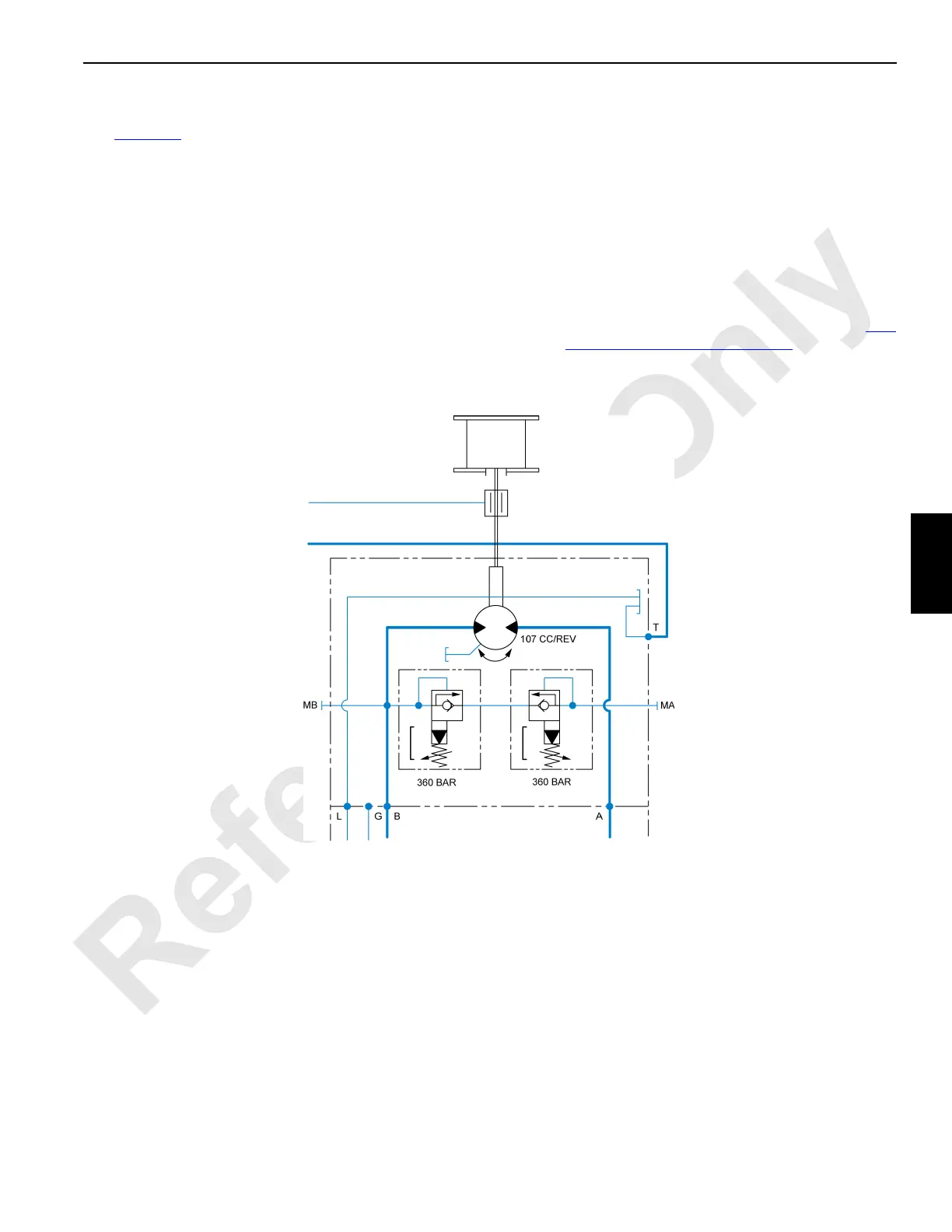
Drum 3 and Drum 4 Motor
See Figure 5-4.
The fixed axial piston motors for hoists 3 and 4 are identical.
Speed is governed by the position of the hoist control handle.
Internal leakage exits via a tank port. Cooling is
accomplished by working flow.
Pressure Relief
For motor protection, each motor has two pilot-operated
pressure-relief valves, one for hoisting and one for lowering.
Relief pressure is factory-set to (5,217 psi) 360 bar.
Test Meter Ports
Ports MA and MB are for connecting a pressure test meter to
the respective work flow circuit.
Speed Sensor
When a drum motor rotates, a hall-effect sensor mounted on
the motor sends an input voltage to the designated node
controller. The controller in turn sends corresponding voltage
pulses to the rotation indicator in the control handle.
NOTE If the drum is equipped with a free fall brake, the
motor-mounted speed sensor is not used. In its
place is an external encoder-type sensor. See Free
Fall System (Optional) on page 5-8.
Figure 5-4. Hoist Drum 3 and 4 Motor Diagram
 Loading...


