HOISTS MLC165-1 SERVICE/MAINTENANCE MANUAL
5-6
Published 05-26-17, Control # 238-02
Test Meter Port
Port M1 is in the PCOR output pilot circuit to the
displacement control hydraulic cylinder.
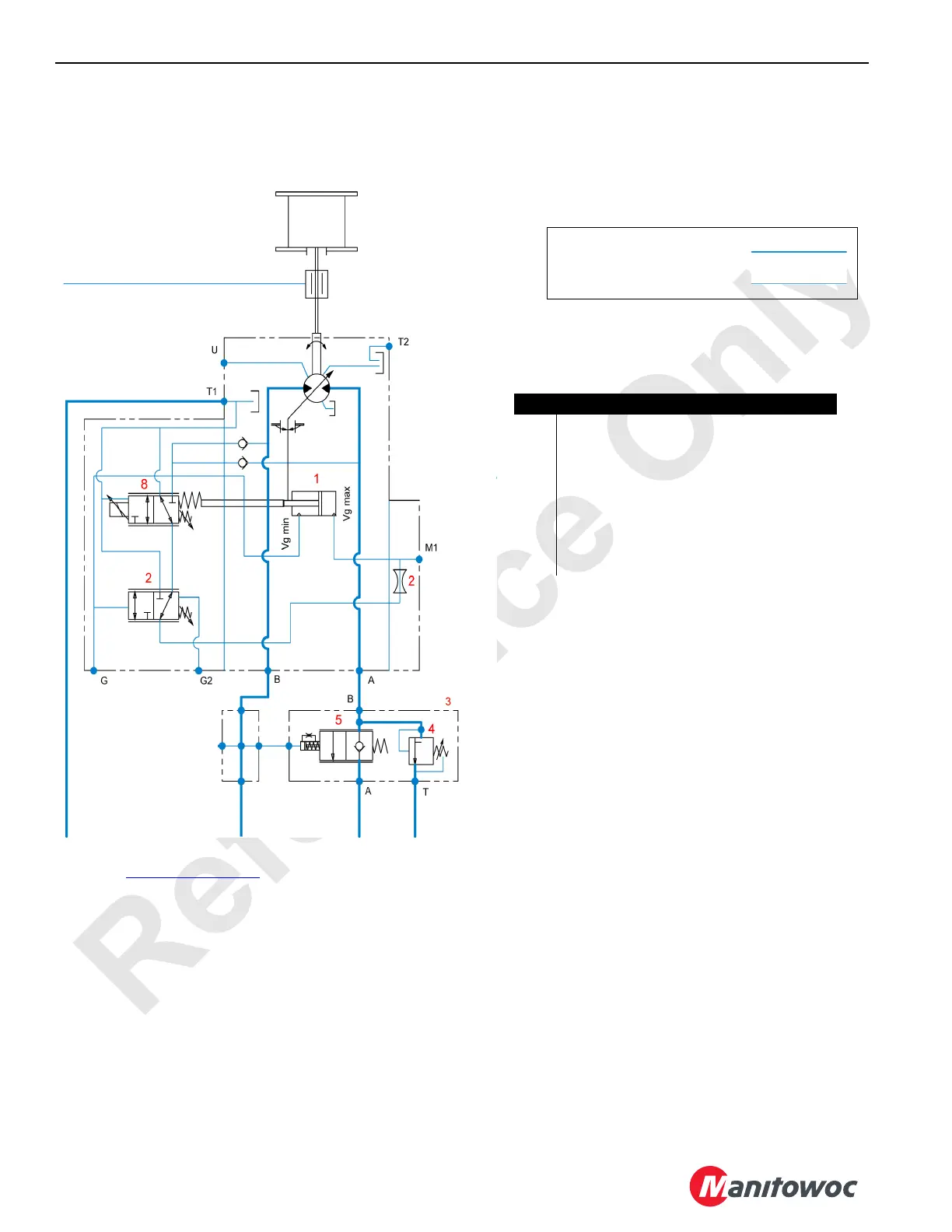
Figure 5-3. Hoist Drum 1 and 2 Motor Hydraulic Diagram
Item Description
1 Motor Displacement Control Actuator
2 Time Delay Orifice
3 Counterbalance Valve Assembly
4 Relief Valve
5 Counterbalance Valve
6 Not Used
7 Pressure Compensation Relief Valve (PCOR)
8 Motor Displacement Control Valve
Pilot or other non-working flow
Working Flow
For continuation of hydraulic circuits, see
Figure 5-2 on page 5-2
.
M100833
 Loading...


