Manitowoc Published 05-26-17, Control # 238-02 10-1
MLC165-1 SERVICE/MAINTENANCE MANUAL ACCESSORIES
SECTION 10
ACCESSORIES
ACCESSORY SYSTEM PRESSURE
All of the accessory system functions are operated at 3,400
psi (234 bar) and 100% displacement of the accessory
pump. All control comes from the manual handles.
CARBODY THEORY OF OPERATION
The carbody valves are handle-actuated spring-centered
proportional valves that control:
• Jack cylinders
• Carbody pin puller cylinders
The accessory pump provides flow to the carbody valve
manifold. Flow from the accessory pump flows to the lower
accessory valve. The lower accessory valve is normally
closed, providing no flow to the lower accessories. When the
operator commands supply fluid to the lower works from the
user interface, node 5 sends a 24Vdc signal to the lower
accessory valve solenoid, energizing it. The valve moves to
the open position and fluid flows through the valve, through
the swivel, and on to the lower carbody valve block. At the
lower carbody valve block, handle-actuated spring-centered
proportional valves drive the individual cylinders.
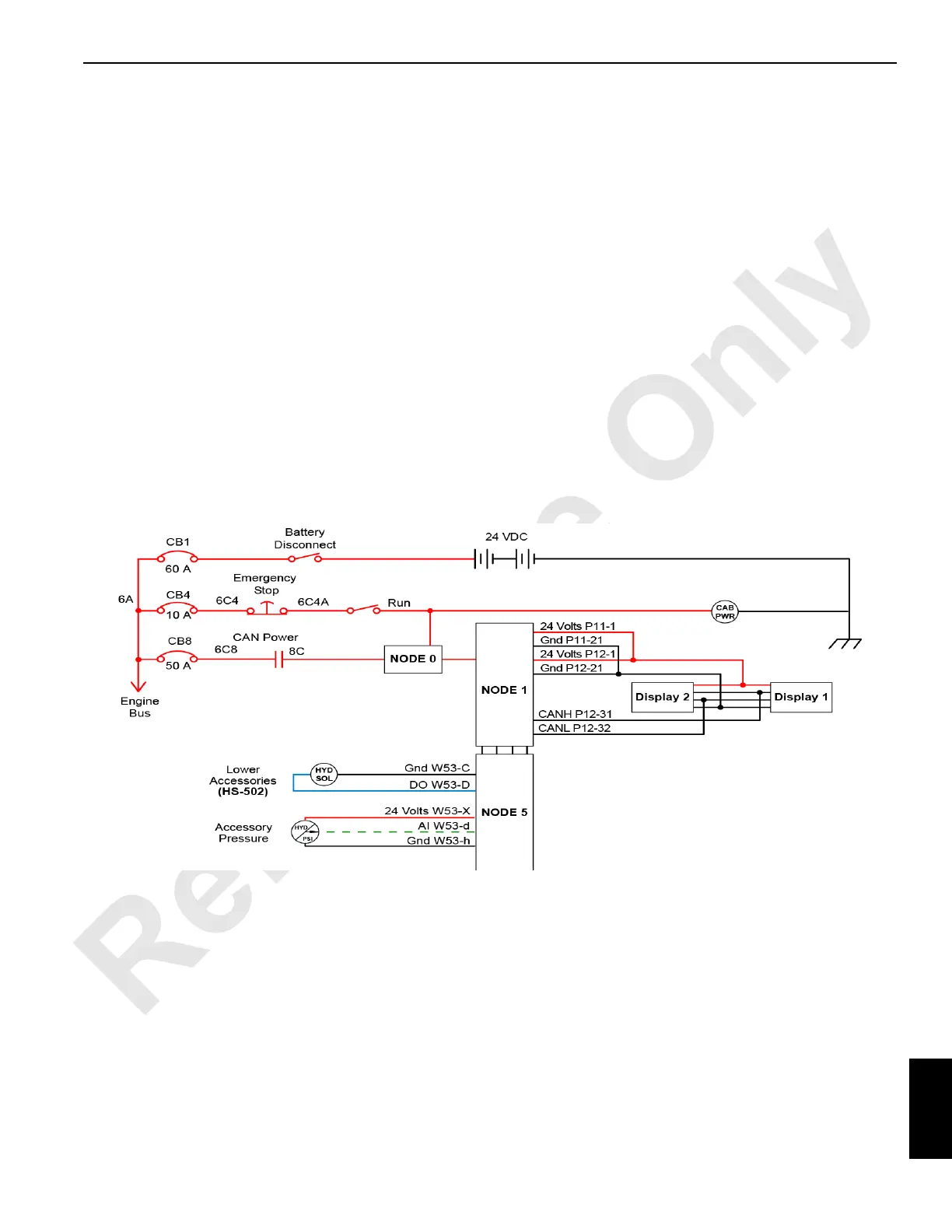
M100850
Figure 10-1. Carbody Electrical Diagram
 Loading...


