ELECTRICAL SYSTEM MLC165-1 SERVICE/MAINTENANCE MANUAL
3-10
Published 05-26-17, Control # 238-02
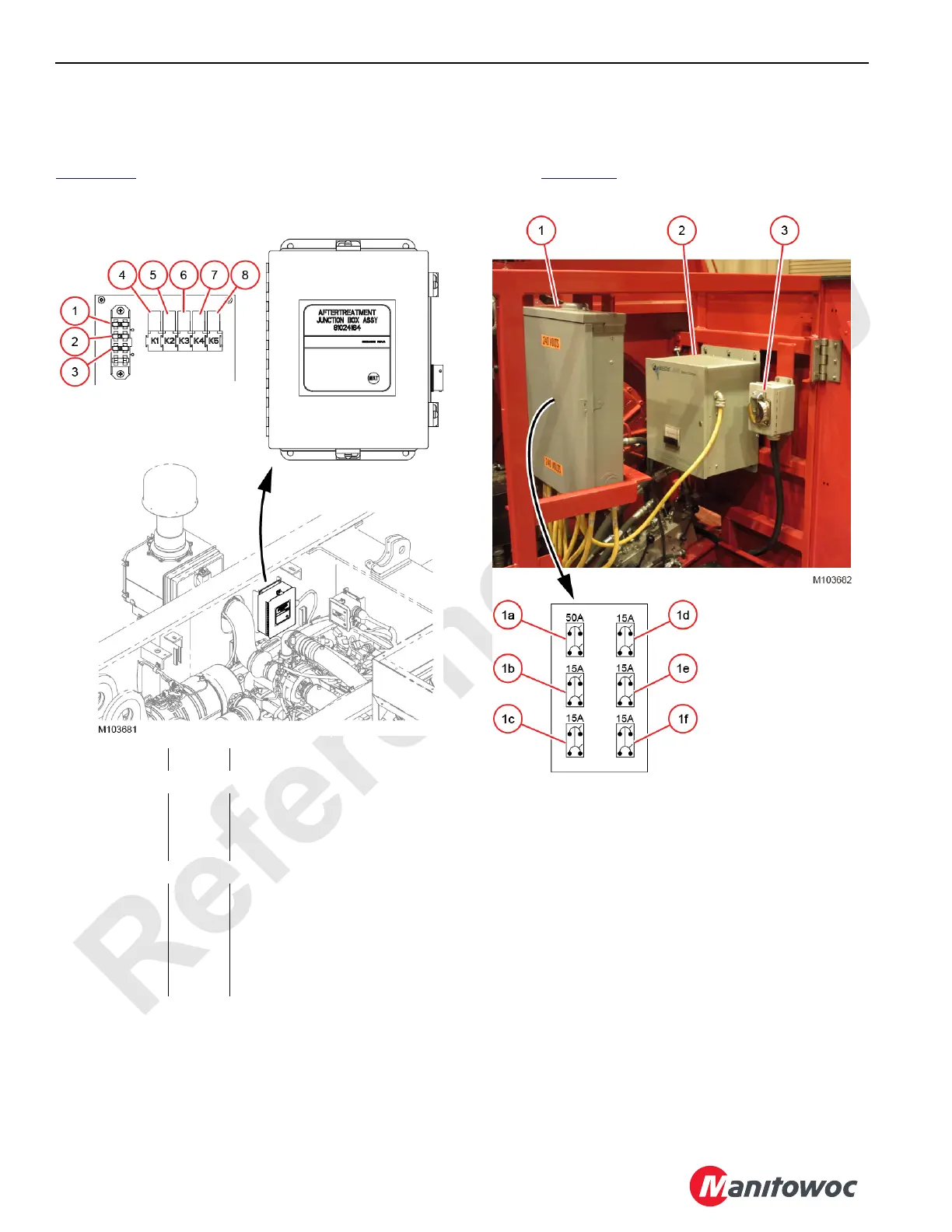
Exhaust Aftertreatment System
For the Tier 4 engine, three circuit breakers and five relays
are located inside the exhaust aftertreatment junction box (1,
Figure 3-15
) mounted in the left-front side of the engine
compartment.
240 VAC Electric System
The circuit breakers for the optional cold weather heater
package and the lighting packages are located in the load
center (1, Figure 3-16
) mounted in the right-side enclosure.
Figure 3-15. Exhaust Aftertreatment Circuit Breakers
Item Amps Description
Circuit Breakers
1 CB-10 15 DEF Supply Module
2 CB-11 10 Aftertreatment Sensors
3 CB-12 15 DEF Heaters
Relays
4 K1 10 DEF Pressure Hose Heater
5 K2 10 DEF Return Hose Heater
6 K3 10 DEF Suction Hose Heater
7 K4 10 DEF Supply Module
8 K5 10 Aftertreatment Sensors
Figure 3-16. 240 VAC Load Center
Item Description
1 Load Center
1a 50A Main Circuit Breaker
1b 15A Circuit Breaker: Rotating Bed Work Lights
1c 15A Circuit Breaker: Boom Work Lights
1d
15A Circuit Breaker: Engine Oil Heater,
Battery Pad Heaters, and Engine Coolant
Heater
1e 15A Circuit Breaker: Hydraulic Tank Heater
1f
15A Circuit Breaker: Cab Console Heater and
Battery Charger
2 Battery Charger
3 240 VAC Receptacle

 Loading...


