POWER TRAIN MLC165-1 SERVICE/MAINTENANCE MANUAL
7-10
Published 05-26-17, Control # 238-02
ENGINE ENCLOSURE
The engine components can be accessed from the doors,
panels, and grating shown in Figure 7-7
Do not operate the crane without the grating and covers
panels in place and all the fasteners secured.
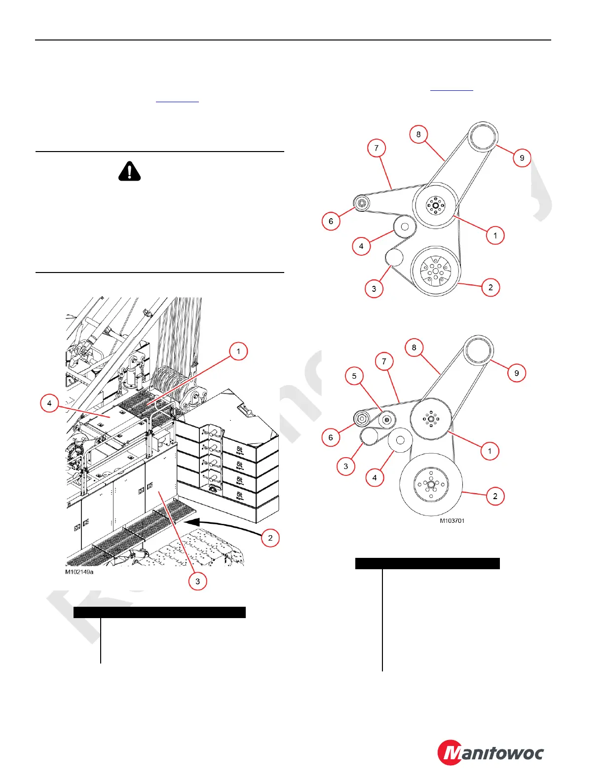
ENGINE BELT ROUTING
Engine belt routing is shown in Figure 7-8 to help the service
personnel when installing new belts on the engine.
WARNING
Personal Injury Hazard
Alert operator before going under rear of rotating bed.
Operator, turn on swing park and do not swing while
personnel are under rear of rotating bed.
To prevent serious injury, use the appropriate lifting
equipment when lifting or removing grating or covers over
engine.
Figure 7-7. Engine Access
Item Description
1 Grating Assembly: 82 lb (37 kg)
2 Under Rear of Rotating Bed
3 Left-Rear Enclosure
4 Engine Cover (2): 33 lb (15 kg) each
Figure 7-8. Engine Belt Routing
Tier 4 Final Engine
Tier 3 Final Engine
Item Description
1 Accessory Drive Pulley
2 Crankshaft Pulley
3 Tensioner
4 Water Pump
5 Idler
6 Alternator
7Belt
8Belt
9 Air Conditioner Compressor
 Loading...


