POWER TRAIN MLC165-1 SERVICE/MAINTENANCE MANUAL
7-4
Published 05-26-17, Control # 238-02
Storage
When the crane is left idle for prolonged periods, the
batteries should be periodically charged.
When storing a battery, make sure it is least 75% charged to
prevent sulfation and the possibility of freezing.
Follow your battery dealer’s recommendations.
BATTERY DISCONNECT SWITCH
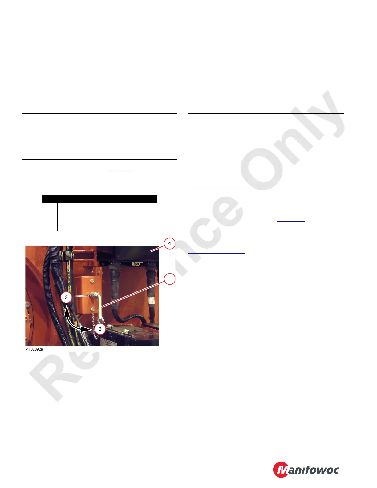
The battery disconnect switch (1, Figure 7-3) is located in the
right-side enclosure next to the engine Node 0.
The switch disconnects the engine controller (Node 0) from
the positive side of the battery. Since the rest of the crane’s
control system is powered through Node 0, opening the
disconnect switch effectively removes power from the entire
control system.
To operate the battery disconnect switch:
• Turn handle COUNTERCLOCKWISE to DISCONNECT
the control system to the battery (handle vertical and
removable).
• Turn handle CLOCKWISE to CONNECT the control
system from the battery (handle horizontal).
The following are reasons for using the disconnect switch:
• When servicing crane’s electrical control system
• To help prevent the batteries from discharging when the
crane is stored for extended periods of time
• To prevent the crane from being started by unauthorized
personnel
BATTERY CHARGER
When a customer supplied 240VAC power source is
connected to the receptacle (4, Figure 7-4
), the optional
battery charger will supply up to 10 amps of 24V power to the
crane batteries.
If an alternative method of charging is desired, see
Charging
on page 7-3.
If the crane is not to be used for more than a few days,
the charger should be plugged in to a 240VAC source.
There is a 20A fuse on the DC output. For charger
troubleshooting and maintenance information, refer to the
manufacturer’s service manual.
ENGINE CONTROLS
See the engine start procedure in Section 3 of the MLC165-1
Operator Manual for engine startup. See the Cummins
engine manual for detailed engine instructions.
The engine is started and stopped with the engine key
switch.
The speed of the crane motors and actuating cylinders
depends on engine speed and equipment control handle
movement. Engine speed is controlled with the hand throttle
or foot throttle and is monitored with a speed sensor. Node 1
controller and engine Node 0 controller control and process
engine information, which is shown on the main display.
The emergency stop push button stops the engine in an
emergency. All brakes will apply and any functions will stop
abruptly.
CAUTION
Avoid Engine Damage
To avoid possible engine fault codes and undesirable
operation, make sure the ignition switch has been off five
minutes before disconnecting the batteries.
Figure 7-3. Battery Disconnect Switch
Item Description
1 Battery Disconnect Switch
2 Disconnected (handle can be removed)
3 Connected
4 Engine Node 0
CAUTION
Avoid Control System Damage
Before Welding:
• Disconnect the battery cables at the batteries.
• Disconnect the cabling from any control node
enclosures that are in the vicinity of the welding.
Do not rely on the disconnect switch to protect the crane’s
electronic systems when welding.

 Loading...


