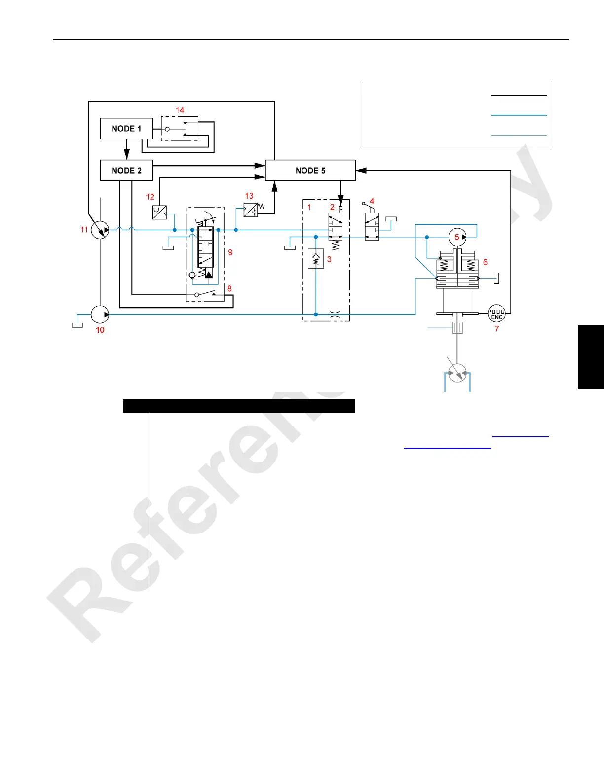
Figure 5-6. System Diagram—Free Fall Components
Item Description
1 Free Fall Manifold
2 Free Fall Enable Solenoid
3 Check Valve
4 Manual On-Off Valve
5 Internal Pump, Free Fall Brake
6 Free Fall Brake Assembly
7 Drum Speed Encoder
8 Pedal Safety Latch Switch
9Brake Pedal
10 Brake Cooling Pump
11 Accessory Pump
12 Pressure Transducer
13 Pressure Switch
14 Free Fall Drum Select/Enable Key Switch
For the remainder of the hoist hydraulic
system diagram, see Hoist System
Diagram on page 5-2
Pilot or other non-working flow
Working Flow
Electrical Connection
M100862
 Loading...


