Manitowoc Published 05-26-17, Control # 238-02 3-21
MLC165-1 SERVICE/MAINTENANCE MANUAL ELECTRICAL SYSTEM
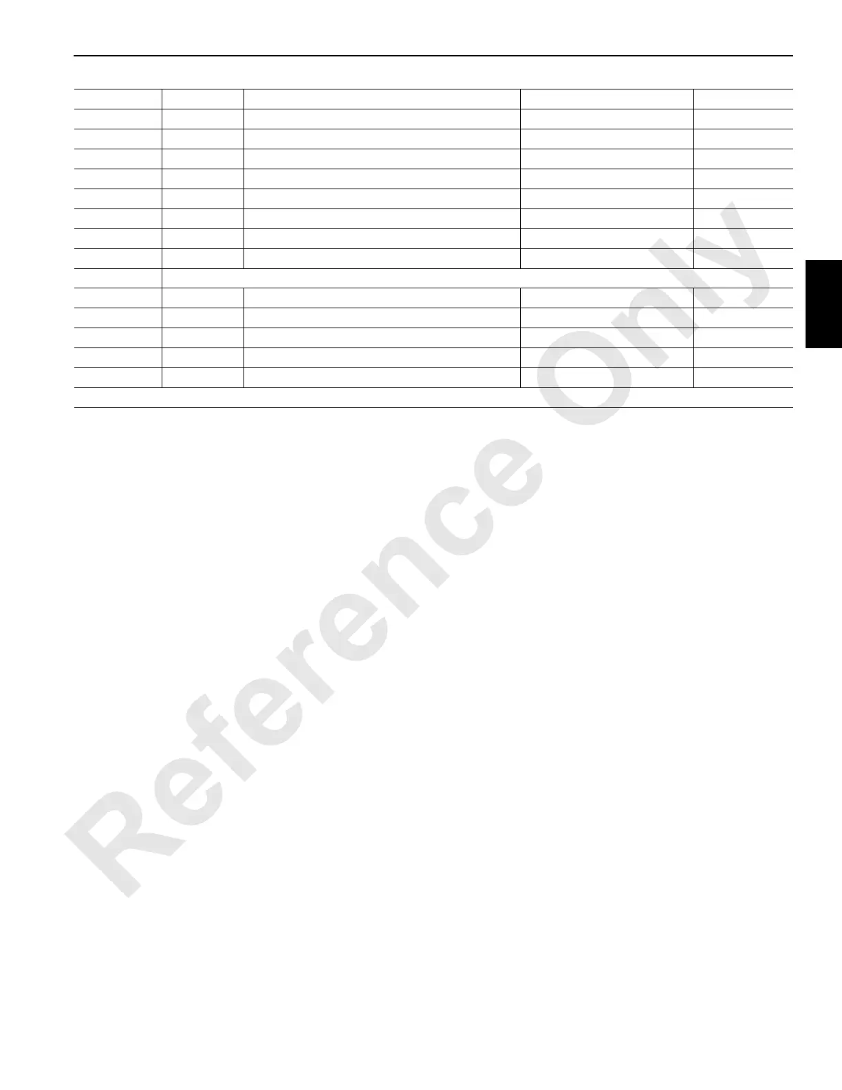
P52-15 DO-1
RCI Beacon Light Green 0 Volts Off, 24 Volts On CAN20-1-1
P52-16 DO-22
System Operation Alarm 0 Volts Off, 24 Volts On CAN20-3-32
P52-17 DO-24
Rated Capacity Indicator/Limiter Fault Alarm 0 Volts Off, 24 Volts On CAN20-3-128
P52-19 DO-18
Switch - Boom Hinge Pins 24 Volts Nominal CAN20-3-2
P52-20 Ground
Drum 4 Handle (H4) Rotation Indicator Ground
P52-23 Ground
Handle (H1, H2, H3) Rotation Indicator Ground
P52-31 DO-8
Seat Safety Switch 24 Volts Nominal CAN20-1-128
P52-37 DO-23
Foot Throttle 24 Volts Nominal CAN20-3-64
P52-38 DO-20
Engine Fuel Level 24 Volts Nominal CAN20-3-8
J3 Receptacle – Gauge Panel (Not Used Terminal are Omitted)
P53-A Ground
To Node 3 24 Volts Nominal
P53-B Ground
CAN System Ground Ground
P53-C Ground
Cab Frame Ground
P53-E 24 Volts DC
Power to Node 3 Ground
P53-F 24 Volts
System Volts DC 24 Volts Nominal
*1 – Lower four bits can be multiplied by 5 or 10 depending on sender, then divided by 16 for an estimation of sender voltage.

 Loading...


