3-14 Published 08/16/19 Control # 112-05
ELECTRIC SYSTEM 500E2 SERVICE MANUAL
screwdriver. Release the screwdriver and the connection is
complete. This connector will accept wire sizes from 14
gauge to 22 gauge wire.
When connecting the individual wires, be sure that the
connector clamps onto the bare stripped wire only! If any
wire insulation gets into the connector, this may cause a poor
connection and cause intermittent or complete failure.
Receiver Input and Output
Each unit comes with a connector chart (Chart C) with the
appropriate input and output instruction for your unit. There
are three (3) inputs to the receiver: (A) BNC connector, (B)
Positive DC current, (C) Negative ground. The unit derives
power from a 10 to 24 volt DC power system that is negative
ground. It is required to install a power switch for the receiver
in series (in-line) with the DC power system (battery). Refer
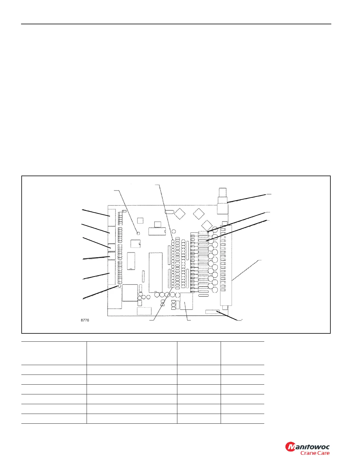
to the Receiver Printed Circuit Board drawing, Figure 3-6.
1. When power is supplied to the receiver the Power
Indicator LED will come on. If not, verify correct polarity
of power and condition of fuse.
2. Turn on the power to the transmitter. At this time the
transmitter will send out a 10 second signal to the
receiver to initialize the system.
a. At this time, the RF Indicator LED and the on-board
relay will be energized. Once the initial 10 seconds
have lapsed, the RF Indicator LED will illuminate
each time the transmitter is activated.
If only the RF Indicator LED illuminates when the
transmitter is activated but does not energize the
relay, verify that the 12 position address switches on
the receiver match those inside the transmitter.
3. Activate each function with the transmitter and notice
that the appropriate output Status Indicator LED
illuminates inside the receiver. (The LED’s parallel to the
orange connector.)
Antenna
Connector
Power Indicator
(1) Spare Fuse
RF Indicator
FIGURE 3-6
Output Status
Indicators
7.5 Amp Fuses
Wago Connector
15 Amp Blade Fuse
Power Relay
Master Control LED
12 Position
Address Switch
Low End
Proportional
High End
Proportional
Bank A
Bank B
Receiver Printed Circuit Board
Description Output Label
NCC Cord Wire
Color
5 Conductor
Cord Wire
Color
N/A Output 16
HCA - RCL Override Output 15 Blu/Red
Turn RH Output 14 Org/Blk
Turn LH Output 13 Bwn/Blk
Boom Up Output 12 Red/Blk
Boom Down Output 11 Yel/Blk

 Loading...


