National Crane Published 08/16/19 Control # 112-05 3-15
500E2 SERVICE MANUAL ELECTRIC SYSTEM
Setup Procedure for the Proportional
Channel
Not all proportional valves are ideal. That is, they do not all
begin to operate at exactly the same voltage nor do they all
reach their full travel at exactly the same voltage. Many
proportional valves work in a narrow “window” of voltage
span. Therefore, a method has been designed to allow the
installer to configure the proportional output to conform to the
proportional valves’ characteristics. This allows the
transmitter proportional potentiometer to control the
proportional valve through its entire range of travel.
Once the receiver is installed properly, the following steps
should allow the installer to quickly match the receiver’s
proportional output to the proportional valve. Please refer to
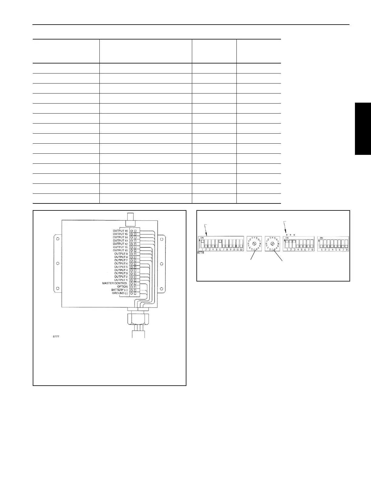
the Receiver Printed Circuit Board drawing, Figure 3-6.
• Low End Proportional — 0 Least Trigger Setting, F
Highest Trigger Setting
• This pot is used to set starting movement on the trigger.
N/A Output 10
N/A Output 9
Tele Retract Output 8 Blu
Tele Extend Output 7 Org
Hoist Up Output 6 Red
Hoist Down Output 5 Brn
N/A Output 4
Throttle Output 3 Red/Blu Blk
Start Output 2 Blk/Blu Org
Ignition Output 1 Blu/Blk Yel
Proportional Master Control Bwn/Red
N/A Option
Battery V+ Battery (+) Blk Red
Ground Ground (-) Yel Blu
Description Output Label
NCC Cord Wire
Color
5 Conductor
Cord Wire
Color
FIGURE 3-7
Insert a small straight blade
screwdriver into the square hole of the
desired pin. Prying towards the face
(lid) of the receiver, insert the
appropriate stripped wire into the
round hole directly below the
screwdriver. Release the screwdriver
and the connection is complete.
FIGURE 3-8
These switches to match
those inside transmitter
12 Position
Address Switch
These (*) switches
to be in ON position
Low End
Proportional
High End
Proportional
Bank A
Bank B
Set Switches as Shown

 Loading...


