SET-UP AND INSTALLATION MLC650 VPC-MAX™ OPERATOR MANUAL
4-130
Published 04-06-18, Control # 231-14
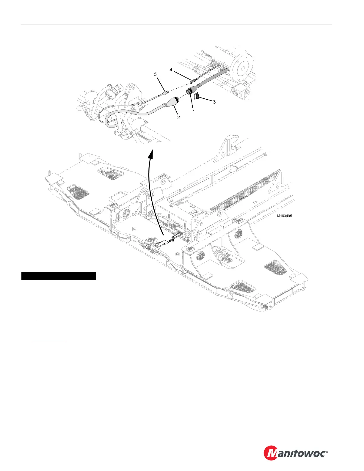
Disconnecting the Electrical Cables
See Figure 4-109 for the following procedure.
1. Disconnect electrical plug WVB2 (4) on the VPC-MAX
beam from electrical plug WVT2-P1 (5) on the
counterweight tray.
2. Remove the dust cap from the terminating resistor (3)
and install the resistor to electrical plug WVB2 on the
beam.
3. Disconnect electrical plug WVB1 (1) on the beam from
electrical plug WVT1-P1 (2) on the tray.
4. Install the dust caps to the plugs.
FIGURE 4-109
Item Description
1 Electrical Plug WVB1
2 Electrical Plug WVT1-P1
3 Terminating Resistor
4 Electrical Plug WVB2
5 Electrical Plug WVT2-P1