Series F Test Frames + IntelliMESUR
®
Software User’s Guide
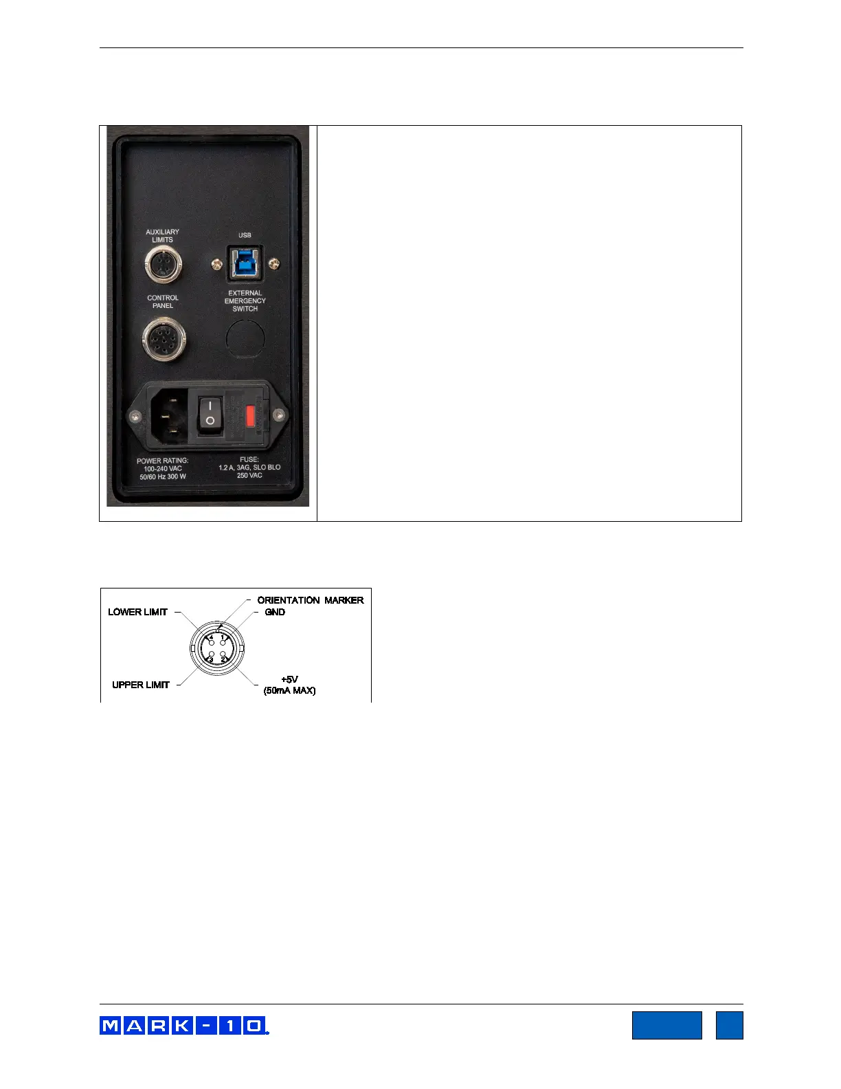
3.5 Connections and outputs
The following connections and outputs are supplied in the rear of the test frame, as shown in the
illustration below:
For interfacing an external limit switch, such as an interlock for a
shield door. A pin diagram is shown in the next sub-section.
USB port
For interfacing with a Windows device running IntelliMESUR.
Control Panel
Inactive.
External Emergency Switch
May be used to connect an optional external emergency stop
switch. May be installed at the factory at time of order, or installed
in the field as a retrofit. Required for use with optional safety
shields. Refer to the Accessory Installation section for
instructions.
Power switch
Refer to the Connecting Power sub-section for important safety
information.
Power plug receptacle
Plug the power cord in here. Refer to the Connecting Power
sub-section for important safety information.
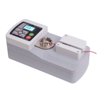
3.5.1 Auxiliary Limits pin diagram
Note that when pins 3 and 4 are not connected, the auxiliary limits are inactive.
When the +5V from pin 2
is connected to either pin 3 or pin 4, the respective limit becomes active and the crosshead is prevented
from movement in that direction.
www.GlobalTestSupply.com
Find Quality Products Online at: sales@GlobalTestSupply.com