Series F Test Frames + IntelliMESUR
®
Software User’s Guide
3. Plug the interlock cable into the corresponding connector in the rear of the test frame column,
labeled “Auxiliary Limits”, as shown in the Connections and Outputs section.
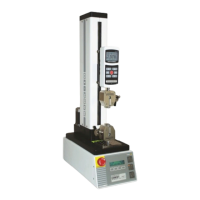
4. Route all cables, such as the test frame power cable and control panel cable, underneath the
shield, as shown below.
Do not route cables through the cutout in the sheet metal cover. Doing so can result
in damage to the cables while the door is rotating past this area. The cutout is
provided only for hand access to the connector panel.
5. The door may be opened in the clockwise or counter-clockwise direction. Magnetic detents are
provided for the closed position. If the interlock cable is plugged in, IntelliMESUR’s status window
displays when the shield is open. When open, IntelliMESUR will not run, except the FollowMe
function in Manual Control, which may be used to adjust the crosshead position.
6. Plug in the cable from the shield into the connector in the rear of the MDU.
14.2 Separating the Column From The Base / Column Extension Installation – F105 / F305 / F505 /
F505H
The column may be separated from the base to accommodate alternative mounting arrangements, for
considerations such as safety, increased sample clearance, integration into existing equipment, etc.
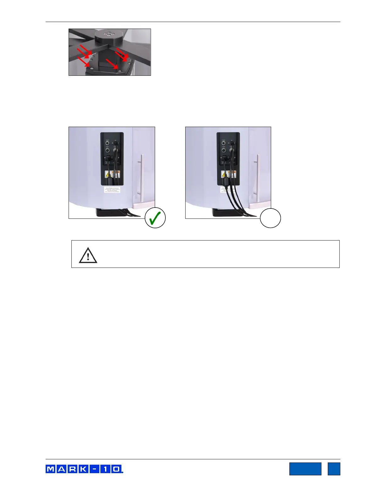
14.2.1 Removing the base from the column
To remove the base, follow these instructions:
1. Power off the test frame and disconnect the power cable.
www.GlobalTestSupply.com
Find Quality Products Online at: sales@GlobalTestSupply.com