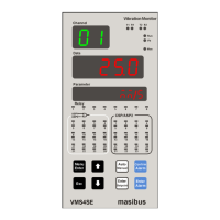
Check the front panel LEDs:
Check the Control LED display Digital Output – Open collector (DO-OC). The corresponding
LED illuminates when the external input signal (Analog Input) is above Control Set point.
Check if the Open collector voltage and current is within the specified value.
Check for looseness of the input prefab cable connector.
Check if the unit is installed correctly.
Check the Alarm LED display Digital Output – Relay (DO-RL). The corresponding LED
illuminates when input signal (Analog Input) is above or below Alarm Set point.
Check if the relay voltage and current is within the specified value.
Check for looseness of the input prefab cable connector.
Check if the unit is installed correctly.
Power supply related:
AC Power voltage (measure at the power terminal block of the unit) 85-265VAC-50/60Hz
(1)
DC Power voltage (measure at the power terminal block of the unit) 18-36VDC
Check for looseness of the power terminal screw- No looseness.
Check for damage of the wiring cable-No damage.
(1)
Unit can also work on 110-370VDC Power Supply range however for this DC range it is not passed
through compliance tests.
Installation state:
Check for looseness of the cable connector and damage of the cable-No looseness or damage.
Ambient environment:
Check if the temperature and humidity are within the specified values.

 Loading...