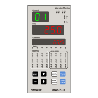
inp.t/p.l.m.per/e.l.m.per/amb/en.unit/sr.no/
prg.dsp/p.l.rec.t/e.l.rec.t
(INP.T/P.L.M.PER/E.L.M.PER/AMB/EN.UNIT/SR.NO/
PRG.DSP/P.L.REC.T/E.L.REC.T)
0: INPUT TYPE
1: Periodic Log Memory Percentage(Optional)
2: Event Log Memory Percentage (Optional)
3: Ambient
4: ENGINEERING UNIT(see Table 23)
(1 to 24 Channels)
5: SERIAL NUMBER(Refer Note : 4)
6: PROGRAMMABLE DISPLAY(Refer Note : 4)
7: Periodic Log record Number(Optional)
8: Event Log Record Number(Optional)
as-cs / as1-as2 / as-os
(AS-CS / AS1-AS2 / AS-OS)
0: ALARM STATUS - CONTROL STATUS
1: ALARM 1 STATUS- ALARM 2 STATUS
2: ALARM STATUS-OPEN COLLECTOR STATUS
(Refer Note : 4)
Note 5 :
1) During Run Mode user can see favorite display on PARAMETER Window. User can see Input
type(of all channels) / Log memory percentage(Optional) / Ambient Temperature /
Engineering Units(Assigned all channels) / Serial Number of the VMS4SE for communication
purpose.
2) User can set the engineering unit to a particular channel. Also user can see the engineering
unit of a particular channel during run mode on PARAMETER Window. Total 33 number of
engineering units are provided with this Product. Different Engineering Units are shown in
Table 23.
3) In programmable display mode, user can program 6 digit Alphanumeric display for channel
name by giving ASCII value of characters “- , . , / , 0 to 9, < , > , A to Z , \ , space”. User can
set different tag name to different channels. Note that, this programmable display can only be
set by means of configuration software and not by front keypad. For more detail, refer Table
501, Table 5151 and Table 51.
4) LED configuration is for displaying different kind of status. It is explained below.
If user wants to see the status of Alarm Status and Control Output Status (Optional),
user needs to set LED = 0 . Thus Alarm Status(here Alarm status is either of Alarm 1
Status or Alarm 2 Status ) and Control Output Status will be displayed (24 LEDs on left

 Loading...