EasyManuals Logo

Masibus Automation VMS4SE User Manual

Masibus Automation VMS4SE
108 pages
To Next Page IconTo Next Page
To Previous Page IconTo Previous Page
Page #34 background imageLoading...
Page #34 background image
User Manual 34
VMS4SE(Vibration Monitor)
REF NO: mVMA/om/101
Issue No: 01
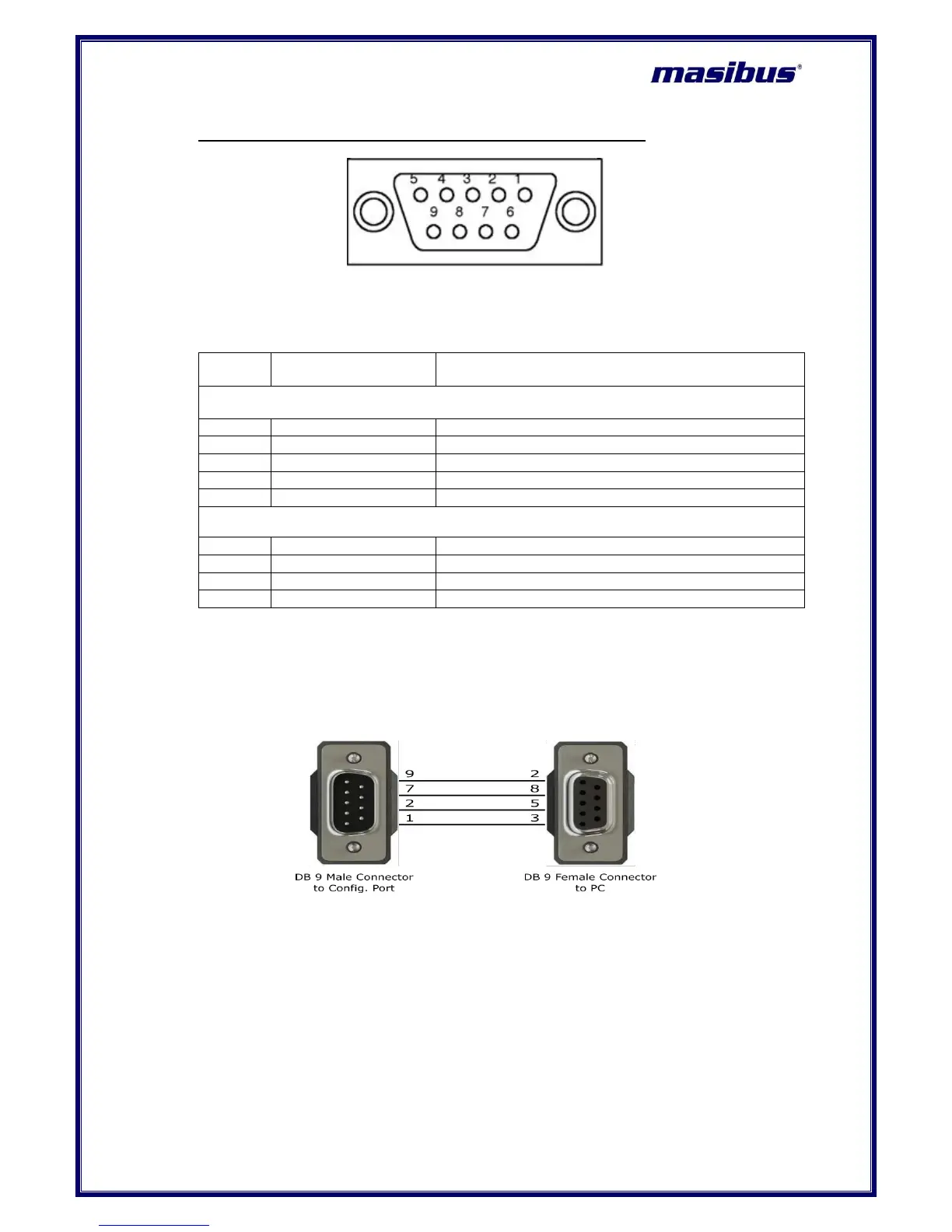
7) PROFIBUS Connection Detail (DB 9 FEMALE at Instrument Side)
Table 11 Pin Details for Profibus Communication (DB 9 Female at Instrument Side)
Pin No.
Signals
Description
DATA AND POWER SIGNALS
3
RxD/TxD-P
Receive/Transmit data; line B
4
CNTR-P
Control of repeater direction
5
DGND
Data ground (reference voltage to VP)
6
VP
Power supply +5v (e.g. for bus termination)
8
RxD/TxD-N
Receive/Transmit data; line A
CONFIGURATION SIGNALS
1
RxD CFG
Receive Data Configuration
2
GND CFG
Ground Configuration
7
RTS CFG
Request to Send - Configuration
9
TxD CFG
Transmit Data Configuration
Note : Make Profibus Configuration Cable as shown in below figure.
Figure 14 Profibus Configuration Cable

Table of Contents

Questions and Answers:

Question and Answer IconNeed help?

Do you have a question about the Masibus Automation VMS4SE and is the answer not in the manual?

Masibus Automation VMS4SE Specifications

General IconGeneral
BrandMasibus Automation
ModelVMS4SE
CategoryMonitor
LanguageEnglish