Home
Masibus Automation
Monitor
VMS4SE
Masibus Automation VMS4SE User Manual
4
of 1
of 1 rating
108 pages
Give review
Manual
Specs
To Next Page
To Next Page
To Previous Page
To Previous Page
Loading...
User Manual
106
VMS4SE(Vibration
Monitor)
REF NO: mVMA
/om/101
Issue No: 01
C.3.5 GSD FILE CONFIGUEATION
Configuration Setting of
GSD File at Profibu
s Master Side:
1.
Select “
mVM
S4SE.GSD
” file b
y locating on CD.
2.
Select
64 wo
rds o
ut
from m
odule list.
3.
Select
32
w
ords out
fr
om module list.
4.
Select
64 wo
rds in
from module list.
5.
Select
64
w
ords in
from modu
le list.
105
107
Table of Contents
Contents
2
Table of Contents
2
List of Tables
3
List of Figures
5
Description of Signs
6
Safety Precautions
6
Contents
7
Product Ordering Code
8
Table 1 Product Ordering Code
8
Table 2 Product Ordering Code Description
8
Table 3 Cable Ordering Code and Description
8
1 Introduction
7
2 Installation
9
Safety Precautions in Installation
9
Mounting of VMS4SE
10
Figure 1 Panel Cutout Dimensions
10
Maintenance and Inspection
11
Figure 2 Side View and TOP View
11
3 Hardware Specification
13
Vibration Input Specification
13
Input Specification(Optional)
13
Table 4 Input Types, Their Ranges, Accuracy and Resolution
13
Output Specification
14
Digital Output- Relay
14
Digital Output- Open Collector(Optional)
14
Analog Output- Retransmission Output(Optional)
14
Buffer Output for Vibration Input
14
Programming and Setting
14
Communication Specification
15
PROFIBUS Communication (Optional)
15
HMI Interface (Optional)
15
Network Connectivity (Optional)
15
Data Logging (Optional)
15
Display Specification
16
Power Supply Specification
16
Signal Isolations and Insulation Specification
16
Table 5 Signal Isolation Specification
16
Construction, Installation, and Wiring Specification
17
Environmental Specification
17
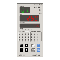
4 Front and Rear Panel Diagram
18
Front Panel Diagram
18
Key Function Description
18
Figure 3 Front Panel Diagram
18
Rear Panel Diagram
19
Figure 4 Rear Panel Diagram
19
Figure 5 Rear Panel Diagram
19
Figure 6 Rear Panel Diagram with AC Supply
20
Figure 7 Rear Panel Diagram with DC Supply
20
5 Connection Diagram
21
Connection Terminal Details
21
Figure 8 Connection Terminals
21
Cable Details
23
Figure 10 Relay Cable Connection (Three Output Terminals)
23
Table 7 Pin Details of Relay Cable (Three Output Terminals)
24
Figure 11 Open Collector Cable Connection
25
Table 8 Pin Details of Open Collector Cable
26
Figure 12 Analog Input Cable Connection
27
Table 9 Pin Details of Analog Input Cable
28
Figure 13 Analog Output Cable Connection
29
Table 10 Pin Details of Analog Output Cable
30
Table 12 Pin Details of Vibration Input Cable
32
Figure 14 Communication Cable Connection
33
Table 13 Pin Details for Profibus Communication (DB 9 Female at Instrument Side)
34
Figure 15 Profibus Configuration Cable
34
6 Brief Operating Procedure
35
Figure 16 Functional Block Diagram of VMS4SE
35
7 Menu Layout
36
Parameter Flow Diagram
36
Figure 17 Program Mode Flow Diagram
36
Figure 18 Configuration Mode Flow Diagram
37
Figure 19 Configuration Mode Flow Diagram
38
Menu Parameters- in Detail
39
Figure 20 Calibration Mode and Security Mode Flow Diagram
39
Table 14 Program Mode Parameters
40
Table 15 Configuration Mode Parameters
41
Table 16 Sub Parameters of Input Configuration Mode
42
Table 17 Input Type Selection
43
Table 18 Sub Parameters of DO(Digital Output) Configuration Mode
43
Table 19 DO(Digital Output) Mapping Number and Its Description
45
Table 20 DO(Digital Output) Description
46
Table 21 Sub Parameters of AO(Analog Output) Configuration Mode (Optional)
46
Table 22 AO(Analog Output)(Retransmission Output) Description
47
Table 23 Sub Parameters of Communication Configuration Mode
48
Table 24 Sub Parameters of Display Configuration Mode
49
Table 25 Different Engineering Units
50
Table 26 Sub Parameters of Logging Configuration Mode
50
Table 27 Sub Parameters of USB Configuration Mode (Optional)
52
Table 28 USB Messages and Description
53
Table 29 Calibration Mode Parameters
54
Table 30 Security Mode Parameters
55
Table 31 Factory Reset Menu
55
8 Alarm Output, Control Output , Digital Output and Watchdog Output Operation
57
Alarm Output Operation
57
Table 32 Alarm 1 and Alarm 2 Momentary Alarm Logic
57
Control Output Operation
59
Basic DO(Digital Output) Function
59
Figure 21 Basic DO(Digital Output) Function
59
Watchdog Timer (WDT) / Watchdog Output Operation
60
9 Calibration Procedure
61
10 Modbus Communication Detail
63
Overview
63
Figure 22 the Query-Response Cycle
63
Exception Responses
64
Modbus Addresses
65
11 Troubleshooting
83
Appendix - a Pv Status During Sensor Burn out Conditions
84
Appendix - B How to Fetch Historical Data
86
Appendix C - Profibus Detail
90
Introduction
90
Communication Protocol
90
Mpc Tool (Masibus Profibus Configuration Tool) V1.X.X.X
102
Preconditions
102
Short Description of Mpc Configuration Tool Installation & Un-Installation
102
Overview Mpc Configuration Tool
103
Starting Mpc Tool
103
Introduction to the Dialog Structure
103
How to Configure Profibus Vibration Monitor
104
Gsd File Configueation
106
Revision History
107
4
Based on 1 rating
Ask a question
Give review
Questions and Answers:
Need help?
Do you have a question about the Masibus Automation VMS4SE and is the answer not in the manual?
Ask a question
Masibus Automation VMS4SE Specifications
General
Brand
Masibus Automation
Model
VMS4SE
Category
Monitor
Language
English
 Loading...