o Valid slave device addresses are in the range of 0 – 247 decimal.
o The individual slave devices are assigned addresses in the range of 1 – 247.
o Address 0 is used for the broadcast address, which all slave devices recognize.
o The data field is constructed using sets of two hexadecimal digits, in the range of 00 to FF
hexadecimal.
o In RTU mode, messages include an error–checking field that is based on a
Cyclical Redundancy Check (CRC) method
o The CRC field is two bytes, containing a 16–bit binary value. The CRC value is
Calculated by the transmitting device, which appends the CRC to the message
Use only following function codes for data read/write purpose
Table 36 Modbus Function code description
10.2 Exception Responses
Except for broadcast messages, when a master device sends a query to a slave
Device it expects a normal response. One of four possible events can occur from
The master‟s query:
If the slave device receives the query without a communication error, and can handle the
query normally, it returns a normal response.
If the slave does not receive the query due to a communication error, no Response is
returned. The master program will eventually process a timeout Condition for the query.
If the slave receives the query, but detects a communication error (parity, LRC, or CRC), no
response is returned. The master program will eventually process a timeout condition for the
query.
If the slave receives the query without a communication error, but cannot Handle it (for
example, if the request is to read a non–existent coil or register), The slave will return an
exception response informing the master of the nature of the error.
The exception response message has two fields that differentiate it from a normal Response:
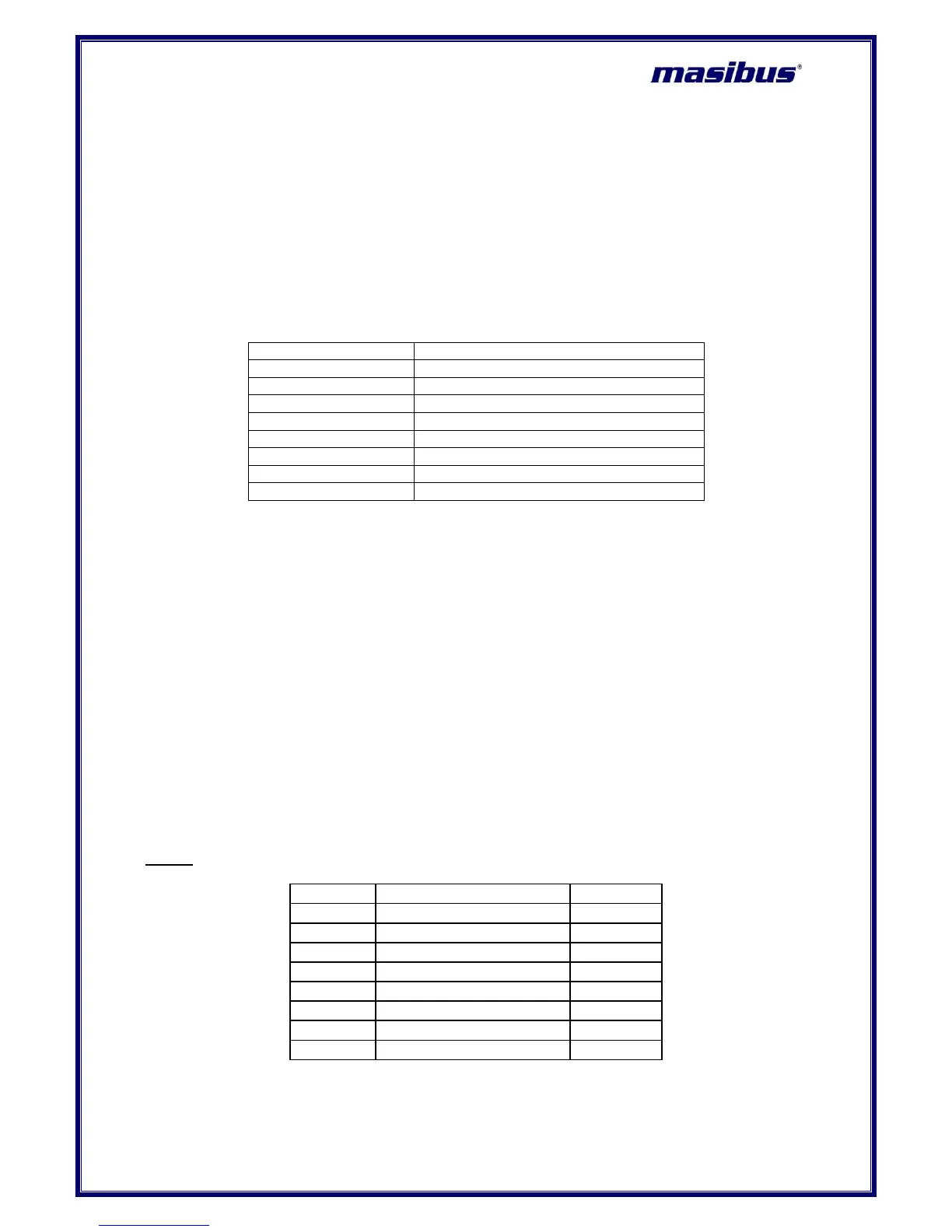
Query:
Table 37 Modbus Query frame format
 Loading...