8.2 Control Output Operation
Control Output is the simplest form of temperature control. The output from the device is either on or
off, with no middle state. For heating control, the output is on when the temperature is below the set
point, and off above set point.
Since the temperature crosses the set point to change the output stage, the process temperature will
be cycling continually, going from above set point to below, and back above. In cases where this
cycling occurs rapidly, and to prevent contactors and valves from getting damaged, an on-off
differential, or “Hysteresis,” is added to the control operations. This Hysteresis assures, if temperature
goes below set point by a certain amount before then only output will turn off or on again. On-Off
Hysteresis prevents the output from “chattering” or making fast, continual switches if the cycling above
and below the set point occurs very rapidly.
Once process value reaches down to set point–Hysteresis value relay will be energized and it will be
ON until process value goes up towards Set point.
Table 32 Control Operation (Optional)
Upon pressing ACK key, acknowledgement will be given for ALARM/TRIP type set point in
abnormal condition.
Note that acknowledgement is not applicable for CONTROL operation.
Alarm Latch function applicable only for ALARM type set point, there is no effect when TRIP or
CTRL type set points are in use.
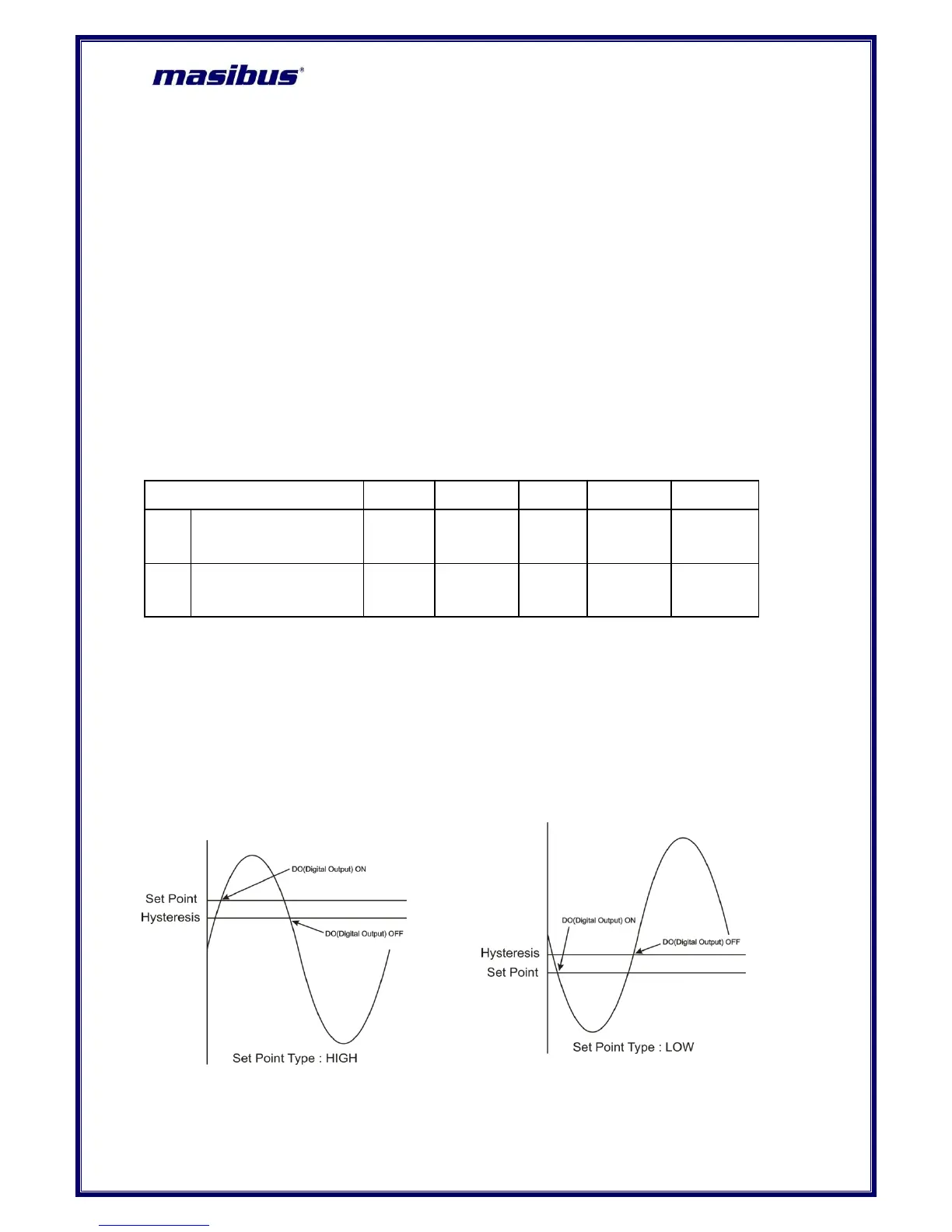
8.3 Basic DO(Digital Output) Function
Figure 20 Basic DO(Digital Output) Function
 Loading...