side will indicate Alarm status and 24 LEDs on right side will indicate Control Output
Status(Optional).
If user wants Alarm 1 Status and Alarm Status 2 to be displayed then user must set
LED =1. Thus Alarm 1 Status and Alarm 2 Status will be displayed (24 LEDs on left side
will indicate Alarm 1 Status and 24 LEDs on right side will indicate Alarm 2 Status.
If user wants Alarm status and Open Collector Output Status (Optional) to be displayed
then user needs to set LED = 2. Thus Alarm Status(here Alarm status is either of Alarm 1
Status or Alarm 2 Status) and Open Collector Output Status will be displayed (24 LEDs
on left side will indicate Alarm status and 24 LEDs on right side will indicate Open
Collector Output Status(Optional).
5) Filter is for Stability of PV data When ever required. Filter = 0 means no filter is applied on PV
data. While Filter = 1 to 10 means Filter of Low value to High value is applied on PV data.
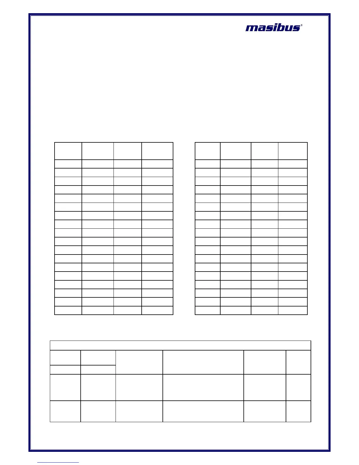
Table 23 Different Engineering Units
 Loading...