VMS4SE(Vibration Monitor)
REF NO: mVMA/om/101
Issue No: 01
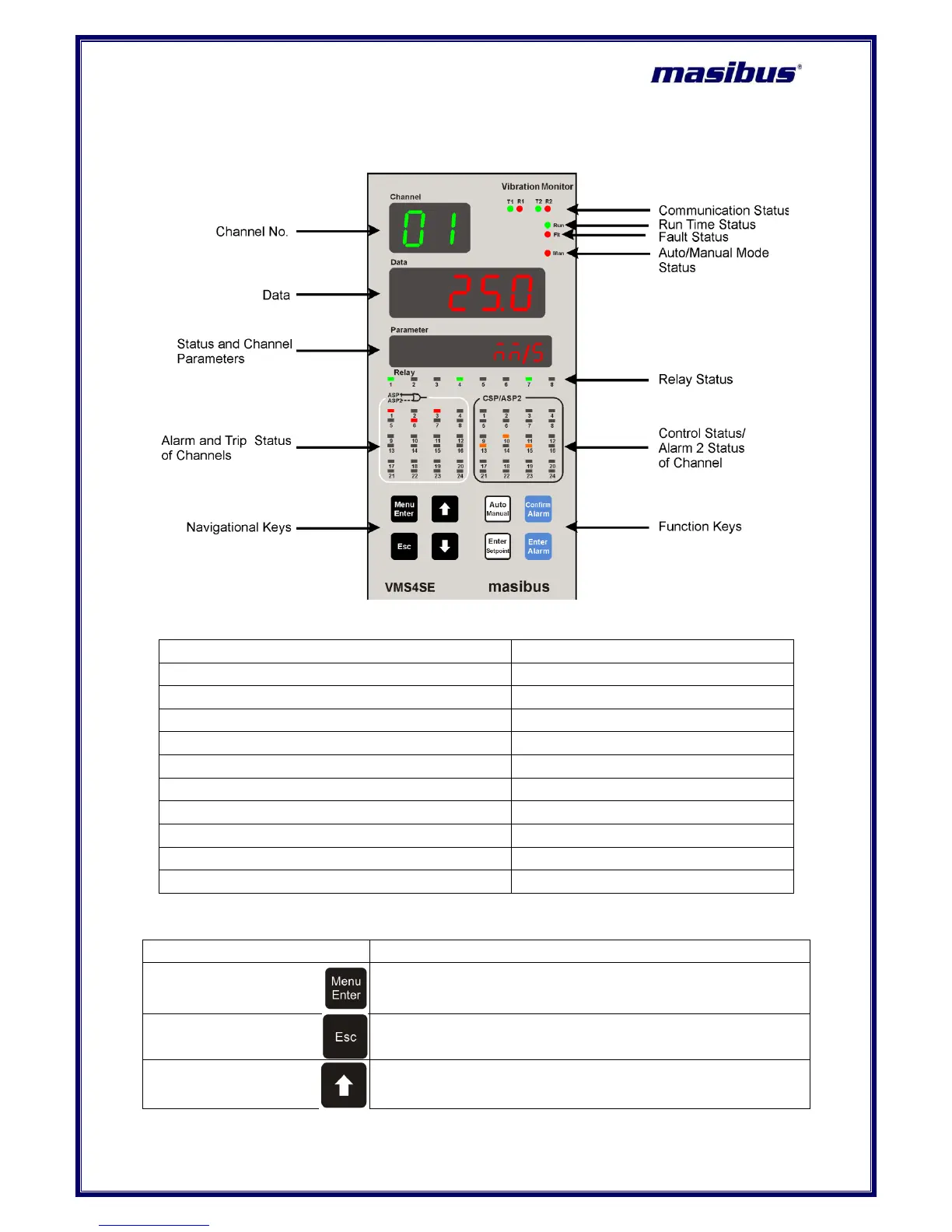
4. FRONT AND REAR PANEL DIAGRAM
4.1 Front Panel Diagram
Figure 3 Front Panel Diagram
Indication on Front Panel
COM-1 RS485 slave indicator LED
COM-2 RS485 master indicator LED
Control / Alarm-2 indicator LED
Alarm-1+Alarm-2 indicator LED
4.2 Key Function Description
It allows Mode Selection when pressed during Run mode, while it
allows saving value of a parameter inside a mode. When inside
any mode, it allows to enter in sub-mode.
It is used to come out from mode/Sub-mode. It is also used to
escape from edit mode without saving the respective parameter.
It is used in increment of value in run mode and other modes
 Loading...