VMS4SE(Vibration Monitor)
REF NO: mVMA/om/101
Issue No: 01
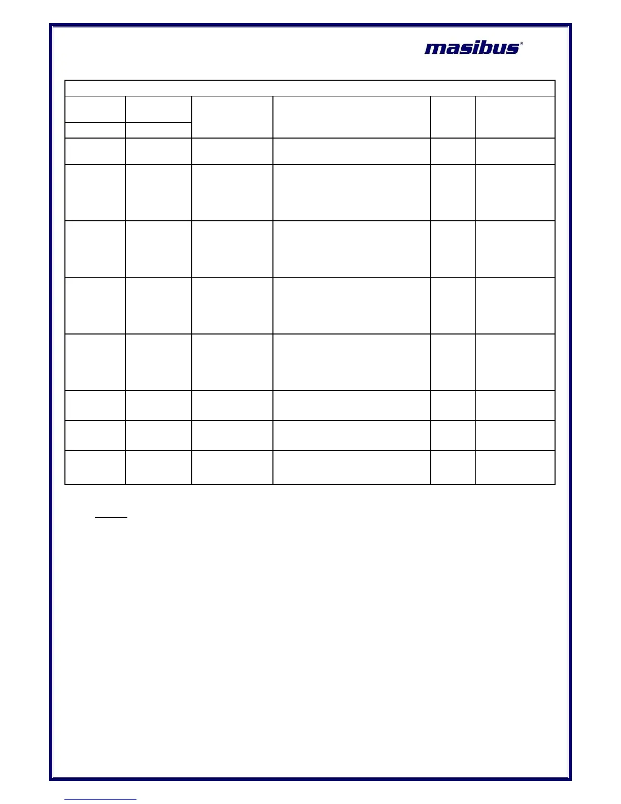
Table 21 Sub Parameters of Communication Configuration Mode
Sub parameters of Communication Configuration Mode
Setting name and description
9600/19.2k// 57.6k
(9600/19.2k)
0: 9600
1: 19.2 K
2: 57.6 K
P.nS.2/P.o.s1/P.ES.1
(P.n.S.2/P.o.S.1/P.o.S.2)
0: PARITY NONE, STOP BIT 2
1:PARITY ODD, STOP BIT- 1
2:PARITY EVEN, STOP BIT- 1
9600/19.2k// 57.6k
(9600/19.2k)
0: 9600
1: 19.2 K
2: 57.6 K
P.nS.2/P.o.s1/P.ES.1
(P.n.S.2/P.o.S.1/P.o.S.2)
0: PARITY NONE, STOP BIT 2
1:PARITY ODD, STOP BIT- 1
2:PARITY EVEN, STOP BIT- 1
Note 4:
1) PARAMETER Window shows sub parameter configuration name.
i.e. while setting Ethernet IP (E.Ip.), Ethernet IP 1(E.ip.1) will be shown on parameter
window. And so on. All sub parameters of Ethernet configuration will be shown as explained.
2) E.IP.1, E.IP.2, E.IP.3 and E.IP.4 is for setting Ethernet IP address. Value should be entered
sequentially. I.e. if Ethernet IP address of 192.168.100.190 needs to be configured, then set
value 192 to E.IP.1, set value 168 to E.IP.2, set value 100 to E.IP.3 and then set value 190 to
E.IP.4.
3) E.msk is for setting Ethernet mask address and E.Gty is for setting Ethernet Gateway
address. Both settings must be set as explained in above note.
 Loading...