LIST OF FIGURES
Figure 1 Panel Cutout Dimensions ....................................................................................................... 10
Figure 2 Side View and TOP view ........................................................................................................ 11
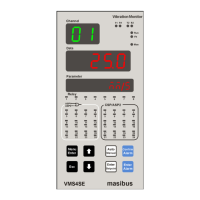
Figure 3 Front Panel Diagram ............................................................................................................... 18
Figure 4 Rear Panel Diagram............................................................................................................. 19
Figure 5 Rear Panel Diagram........................ ....................................................................................... 19
Figure 6 Rear Panel Diagram with AC Supply.................................................................................... 20
Figure 7 Rear Panel Diagram with DC Supply........................... .......................................................... 20
Figure 8 Connection Terminals ............................................................................................................. 21
Figure 10 Relay Cable Connection (Three Output Terminals) ............................................................. 23
Figure 11 Open Collector Cable Connection ........................................................................................ 25
Figure 12 Analog Input Cable Connection ............................................................................................ 27
Figure 13 Analog Output Cable Connection ......................................................................................... 29
Figure 14 Communication Cable Connection ....................................................................................... 33
Figure 15 Profibus Configuration Cable ................................................................................................ 34
Figure 16 Functional Block Diagram of VMS4SE ................................................................................. 35
Figure 17 Program Mode Flow diagram ............................................................................................... 36
Figure 18 Configuration Mode Flow diagram ........................................................................................ 37
Figure 19 Configuration Mode Flow diagram ........................................................................................ 38
Figure 20 Calibration Mode and Security Mode Flow diagram ............................................................. 39
Figure 21 Basic DO(Digital Output) Function........................................................................................ 59
Figure 22 The Query-Response Cycle ................................................................................................ 63
 Loading...