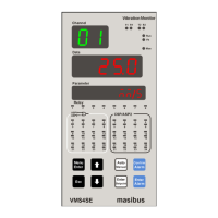
VMS4SE(Vibration Monitor)
REF NO: mVMA/om/101
Issue No: 01
USB fetched data file format
USB data retrieving option
Full Data Fetch (For Periodic and Event Records)
Fetch data by time(approximately) (For Periodic Records
only)
Note : * - With USB port, CE marking is not applicable/valid.
3.9 Display Specification
2-digits, 7-segment, Green , 0.56” character height
4-digits, 7-segment, Red, 0.56‟‟ character height
6-digits, 16-segment Alphanumeric, Orange LEDs, 0.3” character height
24-Red LEDs for Alarm status, 24-Orange LEDs for Control Output, 8-
Green LEDs for Relay status, 1-Red LED for Manual mode, 1- Green
LED for Run mode,1-Red LED for Fault, 2-Green(Rx) & 2-Red(Tx) for
Communication
3.10 Power Supply Specification
85-265VAC-50/60Hz
(1)
/ 100-300VDC or 18-36VDC (Optional)
Max. 16 VA (85-265 VAC) and Max. 8 VA (18-36 VDC)
(1)
Unit can also work on 100-300VDC Power Supply range however for this DC range it is not passed
through compliance tests.
3.11 Signal Isolations And Insulation Specification
Withstanding Voltage:
1) Between primary terminals
(1)
and secondary terminals
(2)
:
1500VAC for 1 minute
2) Between secondary terminals: 500V AC for 1 minute
(1)
Primary terminals indicate power terminals and relay output terminals
(2)
Secondary terminals indicate analog input signals, Digital Contact output terminals, communication
terminals and Ethernet N/W terminal
Signal Isolation Specifications:
Table 5 Signal Isolation Specification
Isolated from other input/output terminals and internal
circuit
Not isolated from other analog input terminals and
from the internal circuit. But isolated from other
input/output terminals.
Isolated from other input/output terminals and internal
circuit
Isolated from other input/output terminals and internal
circuit
Isolated between contact output terminals and
from other Input/output terminals and internal circuit
Isolated from other input/output terminals and internal
circuit
 Loading...