6. BRIEF OPERATING PROCEDURE
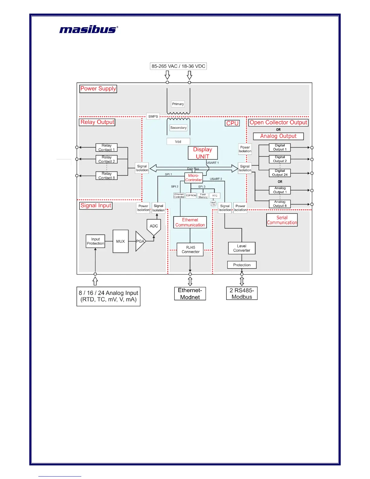
Figure 15 Functional Block Diagram of VMS4SE
Brief Operating Procedure :
1) Connect Digital Output- Relay cable and Open Collector / Analog Output cable , Analog Input
cable and Communication cable to VMS4SE as shown in Error! Reference source not found.,
Figure 9, Figure 10 / Figure 11, Figure 13 respectively.
2) Connect Power supply (Either 85-265 VAC or 18-36 VDC , as per the ordering code) to VMS4SE.
The power on message on display will be “disp Init..”.
3) According to the input type configuration and input sensor feed from field, the Vibration /
temperature / mV / V / mA will be displayed on DATA window and on PARAMETER window user
can choose favorite display parameters like input type of particular channel or log memory
percentage(optional) or engineering unit of particular channel or ambient temperature or serial
number of VMS4SE
. On LED status, user can set Alarm 1 Status – Alarm 2 Status or Alarm
Status – Control Output Status or Alarm Status – Open Collector Status.
4) For in depth parameter details, see following chapters.
 Loading...