5. CONNECTION DIAGRAM
5.1 Connection Terminal Details
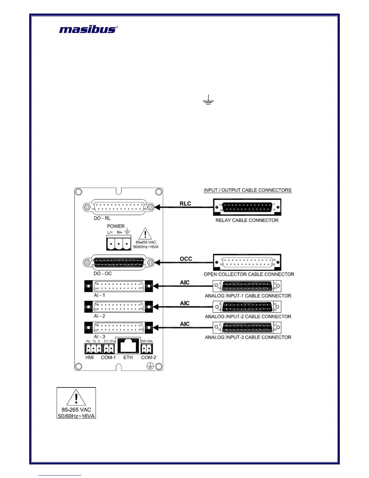
DO – RL Relay Terminals: 16
Pre-Feb. Cable
Power Supply: Live (L/+), Neutral(N/-) and Earth ( )
Pre-Feb. Cable
AI-1,2 and 3 Analog Input: 72 or AI-1 Vibration Input: 4 and AI-2 Analog Input: 8
Pre-Feb. Cable
DO – OC Digital Contact Output: 25 or AO – Analog Contact Output: 16(Optional)
Pre-Feb. Cable
RS-485 Communication: 4
Wire Size: 26- 16AWG
Screw Size: M2.0 Steel Ni Plated
Ethernet Communication: 1
RJ-45 Connector
Figure 8 Connection Terminals
1 Do not touch the terminals of unit when power is ON. It may cause an
electric shock.
2 Wire the power input terminal correctly, and avoid applying any voltage
exceeding the specified voltage range. It may cause failure or damage.

 Loading...